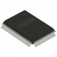
EPC8QI100 Altera, EPC8QI100 Datasheet - Page 10

EPC8QI100
Manufacturer Part Number
EPC8QI100
Description
IC CONFIG DEVICE 8MBIT 100-PQFP
Manufacturer
Altera
Series
EPCr
Datasheet
1.EPC8QC100.pdf
(34 pages)
Specifications of EPC8QI100
Programmable Type
In System Programmable
Memory Size
8Mb
Voltage - Supply
3 V ~ 3.6 V
Operating Temperature
-40°C ~ 85°C
Package / Case
100-MQFP, 100-PQFP
Lead Free Status / RoHS Status
Contains lead / RoHS non-compliant
Other names
544-1239
Available stocks
Company
Part Number
Manufacturer
Quantity
Price
Company:
Part Number:
EPC8QI100
Manufacturer:
ALTERA
Quantity:
10
Company:
Part Number:
EPC8QI100
Manufacturer:
ALTERA
Quantity:
710
Part Number:
EPC8QI100
Manufacturer:
ALTERA
Quantity:
20 000
Company:
Part Number:
EPC8QI100N
Manufacturer:
ALTERA
Quantity:
1 500
Company:
Part Number:
EPC8QI100N
Manufacturer:
ALTERA21
Quantity:
444
1–10
Figure 1–2. FPP Configuration
Notes to
(1) The V
(2) The nINIT_CONF pin is available on enhanced configuration devices and has an internal pull-up resistor that is always active. This means an
(3) The enhanced configuration devices’ OE and nCS pins have internal programmable pull-up resistors. If internal pull-up resistors are used, external
(4) For PORSEL, PGM[], and EXCLK pin connections, refer to
(5) In the 100-pin PQFP package, you must externally connect the following pins: C-A0 to F-A0, C-A1 to F-A1, C-A15 to F-A15, C-A16 to
(6) Connect the FPGA MSEL[] input pins to select the FPP configuration mode. For details, refer to the appropriate FPGA family chapter in the
(7) To protect Intel Flash based EPC devices content, isolate the V
Configuration Handbook (Complete Two-Volume Set)
external pull-up resistor is not required on the nINIT_CONF / nCONFIG line. The nINIT_CONF pin does not need to be connected if its
functionality is not used. If nINIT_CONF is not used, nCONFIG must be pulled to V
pull-up resistors should not be used on these pins. The internal pull-up resistors are used by default in the Quartus
internal pull-up resistors, check the Disable nCS and OE pull-ups on configuration device option when generating programming files.
F-A16, and BYTE# to V
C-RP# to F-RP#, C-WE# to F-WE#, TM1 to V
Configuration
Device Protection” on page
Figure
CC
should be connected to the same supply voltage as the configuration device.
1–2:
1
Handbook.
(6)
N.C.
Multiple FPGAs can be configured using a single enhanced configuration device in
FPP mode. In this mode, multiple Stratix series FPGAs, APEX II FPGAs, or both, are
cascaded together in a daisy chain.
After the first FPGA completes configuration, its nCEO pin asserts to activate the nCE
pin for the second FPGA, which prompts the second device to start capturing
configuration data. In this setup, the FPGAs CONF_DONE pins are tied together, and
hence all devices initialize and enter user mode simultaneously. If the enhanced
configuration device or one of the FPGAs detects an error, configuration stops (and
simultaneously restarts) for the whole chain because the nSTATUS pins are tied
together.
While Altera FPGAs can be cascaded in a configuration chain, the enhanced
configuration devices cannot be cascaded to configure larger devices or chains.
n
CC
. Additionally, you must make the following pin connections in both 100-pin PQFP and 88-pin UFBGA packages:
1–15.
MSEL
nCEO
APEX II Device
Stratix Series
CONF_DONE
or
DATA[7..0]
nSTATUS
nCONFIG
DCLK
nCE
CC
, TM0 to GND, and WP# to V
V
CC
(3)
(1)
GND
V
Chapter 1: Enhanced Configuration Devices (EPC4, EPC8, and EPC16) Data Sheet
CC
Table
(3)
CCW
(1)
(1)
GND
supply from V
1–10.
V
CC
Enhanced Configuration
WP#
BYTE# (5)
TM1
C-A0 (5)
C-A1 (5)
C-A15 (5)
C-A16 (5)
WE#C
RP#C
DCLK
DATA[7..0]
OE
nCS
nINIT_CONF (2)
TMO
(3)
(3)
Device
CC
CC
.
. For more information, refer section
PGM[2..0]
DQ[15..0]
PORSEL
A[20..0]
RY/BY#
EXCLK
VCCW
WE#F
A0-F
A1-F
A15-F
A16-F
RP#F
CC
OE#
CE#
either directly or through a resistor.
V
CC
(4)
(4)
(4)
(7)
N.C.
N.C.
N.C.
N.C.
N.C.
© December 2009 Altera Corporation
®
II software. To turn off the
“Intel-Flash-Based EPC
Functional Description


