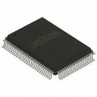
EPC8QI100 Altera, EPC8QI100 Datasheet - Page 14

EPC8QI100
Manufacturer Part Number
EPC8QI100
Description
IC CONFIG DEVICE 8MBIT 100-PQFP
Manufacturer
Altera
Series
EPCr
Datasheet
1.EPC8QC100.pdf
(34 pages)
Specifications of EPC8QI100
Programmable Type
In System Programmable
Memory Size
8Mb
Voltage - Supply
3 V ~ 3.6 V
Operating Temperature
-40°C ~ 85°C
Package / Case
100-MQFP, 100-PQFP
Lead Free Status / RoHS Status
Contains lead / RoHS non-compliant
Other names
544-1239
Available stocks
Company
Part Number
Manufacturer
Quantity
Price
Company:
Part Number:
EPC8QI100
Manufacturer:
ALTERA
Quantity:
10
Company:
Part Number:
EPC8QI100
Manufacturer:
ALTERA
Quantity:
710
Part Number:
EPC8QI100
Manufacturer:
ALTERA
Quantity:
20 000
Company:
Part Number:
EPC8QI100N
Manufacturer:
ALTERA
Quantity:
1 500
Company:
Part Number:
EPC8QI100N
Manufacturer:
ALTERA21
Quantity:
444
1–14
Configuration Handbook (Complete Two-Volume Set)
f
1
The external flash interface signals cannot be shared between multiple enhanced
configuration devices because this causes contention during in-system programming
and configuration. During these operations, the controller chips inside the enhanced
configuration devices are actively accessing flash memory. Therefore, enhanced
configuration devices do not support shared flash bus interfaces.
The enhanced configuration device controller chip accesses flash memory during:
■
■
■
During these operations, the external FPGA or processor must tri-state its interface to
the flash memory. After configuration and programming, the enhanced configuration
device’s controller tri-states the internal interface and goes into an idle mode. To
interrupt a configuration cycle in order to access the flash via the external flash
interface, the external device can hold the FPGA’s nCONFIG input low. This keeps the
configuration device in reset by holding the nSTATUS-OE line low, allowing external
flash access.
For more information about the software support for the external flash interface
feature, refer to the
Configuration Handbook. For details about flash commands, timing, memory
organization, and write protection features, refer to the following documents:
■
■
■
FPGA configuration—reading configuration data from flash
JTAG-based flash programming—storing configuration data in flash
At POR—reading option bits from flash
For Micron flash-based EPC4, refer to the Micron Flash Memory MT28F400B3 Data
Sheet at www.micron.com.
For Sharp flash-based EPC16, refer to the Sharp LHF16J06 Data Sheet Flash Memory
Used in EPC16 Devices at www.sharpsma.com.
For the Intel Advanced Boot Block Flash Memory (B3) 28F008/800B3, 28F016/160B3,
28F320B3, 28F640B3 Datasheet, visit www.intel.com.
Altera Enhanced Configuration Devices
Chapter 1: Enhanced Configuration Devices (EPC4, EPC8, and EPC16) Data Sheet
chapter in volume 2 of the
© December 2009 Altera Corporation
Functional Description


