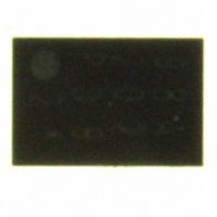
SE98ATP,547 NXP Semiconductors, SE98ATP,547 Datasheet - Page 18

SE98ATP,547
Manufacturer Part Number
SE98ATP,547
Description
IC TEMP SENSOR DDR 8-HWSON
Manufacturer
NXP Semiconductors
Datasheet
1.SE98ATP547.pdf
(43 pages)
Specifications of SE98ATP,547
Function
Temp Monitoring System (Sensor)
Topology
ADC (Sigma Delta), Register Bank
Sensor Type
Internal
Sensing Temperature
-40°C ~ 125°C
Output Type
I²C™/SMBus™
Output Alarm
Yes
Output Fan
Yes
Voltage - Supply
1.7 V ~ 3.6 V
Operating Temperature
-40°C ~ 125°C
Mounting Type
Surface Mount
Package / Case
8-WSON (Exposed Pad), 8-HWSON
Temperature Threshold
Programmable
Full Temp Accuracy
+/- 1 C
Digital Output - Bus Interface
2-Wire, SMBus, I2C
Digital Output - Number Of Bits
11
Supply Voltage (max)
3.6 V
Supply Voltage (min)
1.7 V
Description/function
DDR Memory Module Temperature Sensor
Maximum Operating Temperature
+ 125 C
Minimum Operating Temperature
- 40 C
Supply Current
250 uA
Lead Free Status / RoHS Status
Lead free / RoHS Compliant
Other names
568-4731-2
SE98ATP,147
SE98ATP,147
NXP Semiconductors
Table 8.
SE98A_4
Product data sheet
Bit
Symbol
Default
Access
Bit
Symbol
Default
Access
Configuration register (address 01h) bit allocation
CTLB
8.3 Configuration register (01h, 16-bit read/write)
R/W
15
R
0
7
0
Table 9.
Bit
15:11
10:9
8
AWLB
R/W
14
R
0
6
0
Symbol
RFU
HEN
SHMD
Configuration register (address 01h) bit description
CEVNT
Description
reserved for future use; must be ‘0’.
Hysteresis Enable
When enabled, hysteresis is applied to temperature movement around trigger
points. For example, consider the behavior of the ‘Above Alarm Window’ bit
(bit 14 of the Temperature register) when the hysteresis is set to 3 °C. As the
temperature rises, bit 14 will be set to 1 (temperature is above the alarm
window) when the Temperature register contains a value that is greater than
the value in the Alarm Temperature Upper Boundary register. If the
temperature decreases, bit 14 will remain set until the measured temperature
is less than or equal to the value in the Alarm Temperature Upper Boundary
register minus 3 °C. (Refer to
Similarly, the ‘Below Alarm Window’ bit (bit 13 of the Temperature register) will
be set to 0 (temperature is equal to or above the Alarm Window Lower
Boundary Trip register) when the value in the Temperature register is equal to
or greater than the value in the Alarm Temperature Lower Boundary register.
As the temperature decreases, bit 13 will be set to 1 when the value in the
Temperature register is equal to or less than the value in the Alarm
Temperature Lower Boundary register minus 3 °C. Note that hysteresis is also
applied to EVENT pin functionality.
When either of the Critical Trip or Alarm Window lock bits is set, these bits
cannot be altered until unlocked.
Shutdown Mode.
When shut down, the thermal sensor diode and Analog-to-Digital Converter
(ADC) are disabled to save power, no events will be generated. When either of
the Critical Trip or Alarm Window lock bits is set, this bit cannot be set until
unlocked. However, it can be cleared at any time.
RFU
R/W
13
R
0
5
0
00 — Disable hysteresis (default)
01 — Enable hysteresis at 1.5 °C
10 — Enable hysteresis at 3 °C
11 — Enable hysteresis at 6 °C
0 — Enabled Temperature Sensor (default)
1 — Disabled Temperature Sensor
Rev. 04 — 25 November 2009
ESTAT
R/W
12
R
0
0
4
DDR memory module temp sensor, 1.7 V to 3.6 V
EOCTL
R/W
11
R
0
3
0
Figure 6
and
R/W
CVO
R/W
10
Table
0
2
0
HEN[1:0]
10).
R/W
R/W
EP
9
0
1
0
© NXP B.V. 2009. All rights reserved.
SE98A
SHMD
EMD
R/W
R/W
8
0
0
0
18 of 43


