EVAL-ADUC832QSZ Analog Devices Inc, EVAL-ADUC832QSZ Datasheet - Page 75
EVAL-ADUC832QSZ
Manufacturer Part Number
EVAL-ADUC832QSZ
Description
KIT DEV FOR ADUC832 QUICK START
Manufacturer
Analog Devices Inc
Series
QuickStart™ Kitr
Type
MCUr
Specifications of EVAL-ADUC832QSZ
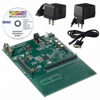
Contents
Evaluation Board, Cable, Power Supply, Software and Documentation
Lead Free Status / RoHS Status
Lead free / RoHS Compliant
For Use With/related Products
ADuC832
Lead Free Status / RoHS Status
Compliant, Lead free / RoHS Compliant
Other names
EVAL-ADUC832QS
EVAL-ADUC832QS
EVAL-ADUC832QS


UART SERIAL INTERFACE
The serial port is full duplex, meaning it can transmit and
receive simultaneously. It is also receive-buffered, meaning it
can commence reception of a second byte before a previously
received byte has been read from the receive register. However,
if the first byte still has not been read by the time reception of
the second byte is complete, the first byte is lost. The physical
interface to the serial data network is via the RXD and TXD
pins, and the SFR interface to the UART is comprised of SBUF
and SCON.
Table 40. SCON SFR Bit Designations
Bit
[7:6]
[5]
[4]
[3]
[2]
[1]
[0]
Name
SM[0:1]
SM2
REN
TB8
RB8
TI
RI
Description
UART serial mode select bits. These bits select the serial port operating mode as follows:
SM0
0
0
1
1
Multiprocessor communication enable bit.
Enables multiprocessor communication in Mode 2 and Mode 3. In Mode 0, SM2 should be cleared. In Mode 1, if SM2 is set,
RI is not activated if a valid stop bit was not received. If SM2 is cleared, RI is set as soon as the byte of data has been
received. In Mode 2 or Mode 3, if SM2 is set, RI is not activated if the received ninth data bit in RB8 is 0. If SM2 is cleared, RI
is set as soon as the byte of data has been received.
Serial port receive enable bit.
Set by user software to enable serial port reception.
Cleared by user software to disable serial port reception.
Serial Port Transmit Bit 9.
The data loaded into TB8 is the ninth data bit that is transmitted in Mode 2 and Mode 3.
Serial Port Receiver Bit 9.
The ninth data bit received in Mode 2 and Mode 3 is latched into RB8. For Mode 1, the stop bit is latched into RB8.
Serial port transmit interrupt flag.
Set by hardware at the end of the eighth bit in Mode 0, or at the beginning of the stop bit in Mode 1, Mode 2, and Mode 3.
TI must be cleared by user software.
Serial port receive interrupt flag.
Set by hardware at the end of the eighth bit in Mode 0, or halfway through the stop bit in Mode 1, Mode 2, and Mode 3.
RI must be cleared by software.
SM1
0
1
0
1
Selected Operating Mode
Mode 0: shift register, fixed baud rate (Core_CLK/2)
Mode 1: 8-bit UART, variable baud rate
Mode 2: 9-bit UART, fixed baud rate (Core_CLK/64) or (Core_CLK/32)
Mode 3: 9-bit UART, variable baud rate
Rev. A | Page 75 of 92
SBUF
The serial port receive and transmit registers are both accessed
through the SBUF SFR (SFR address = 99H). Writing to SBUF
loads the transmit register and reading SBUF accesses a
physically separate receive register.
SCON (UART SERIAL PORT CONTROL REGISTER)
SFR Address:
Power-On Default Value:
Bit Addressable:
98H
00H
Yes
ADuC832
Related parts for EVAL-ADUC832QSZ
Image
Part Number
Description
Manufacturer
Datasheet
Request
R


Part Number:
Description:
BOARD EVAL FOR SI270X-A
Manufacturer:
Silicon Laboratories Inc
Datasheet:

Part Number:
Description:
BUCK CONV REF DESIGN KIT IP1201
Manufacturer:
International Rectifier
Datasheet:
Part Number:
Description:
BOARD DEMO SYNC DUAL BUCK CNVTER
Manufacturer:
International Rectifier
Datasheet:
Part Number:
Description:
BOARD DEMO SYNC BUCK CONVETER
Manufacturer:
International Rectifier
Datasheet:

Part Number:
Description:
EVALBOARD/EB Omnidirectional microphone - Analog
Manufacturer:
Analog Devices
Datasheet:
Part Number:
Description:
EVALBOARD/EB Omnidirectional microphone - Analog
Manufacturer:
Analog Devices
Datasheet:


Part Number:
Description:
BOARD EVAL LED DRIVER LT3756
Manufacturer:
Linear Technology
Datasheet:

Part Number:
Description:
BOARD EVAL FOR AD7741/7742
Manufacturer:
Analog Devices Inc
Datasheet:

Part Number:
Description:
±1.7g Dual-Axis IMEMS Accelerometer Evaluation Board
Manufacturer:
Analog Devices Inc
Datasheet:

Part Number:
Description:
IC MULTIPLIER ANALOG 8-SOIC T/R
Manufacturer:
Analog Devices Inc
Datasheet:

Part Number:
Description:
IC ANALOG MULTIPLIER 8-DIP
Manufacturer:
Analog Devices Inc
Datasheet:
Part Number:
Description:
IC ANALOG MULTIPLIER 8-SOIC
Manufacturer:
Analog Devices Inc
Datasheet:
Part Number:
Description:
IC ANALOG MULTIPLIER 8-DIP
Manufacturer:
Analog Devices Inc
Datasheet: