EVAL-ADUC832QSZ Analog Devices Inc, EVAL-ADUC832QSZ Datasheet - Page 77
EVAL-ADUC832QSZ
Manufacturer Part Number
EVAL-ADUC832QSZ
Description
KIT DEV FOR ADUC832 QUICK START
Manufacturer
Analog Devices Inc
Series
QuickStart™ Kitr
Type
MCUr
Specifications of EVAL-ADUC832QSZ
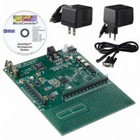
Contents
Evaluation Board, Cable, Power Supply, Software and Documentation
Lead Free Status / RoHS Status
Lead free / RoHS Compliant
For Use With/related Products
ADuC832
Lead Free Status / RoHS Status
Compliant, Lead free / RoHS Compliant
Other names
EVAL-ADUC832QS
EVAL-ADUC832QS
EVAL-ADUC832QS


UART SERIAL PORT BAUD RATE GENERATION
Mode 0 Baud Rate Generation
The baud rate in Mode 0 is fixed.
Mode 2 Baud Rate Generation
The baud rate in Mode 2 depends on the value of the SMOD bit
in the PCON SFR. If SMOD = 0, the baud rate is 1/64 of the
core clock. If SMOD = 1, the baud rate is 1/32 of the core clock:
Mode 1 and Mode 3 Baud Rate Generation
The baud rates in Mode 1 and Mode 3 are determined by the
overflow rate in Timer 1 or Timer 2, or both (one for transmit
and the other for receive).
TIMER 1 GENERATED BAUD RATES
When Timer 1 is used as the baud rate generator, the baud rates
in Mode 1 and Mode 3 are determined by the Timer 1 overflow
rate and the value of SMOD as follows:
The Timer 1 interrupt should be disabled in this application.
The timer itself can be configured for either timer or counter
operation, and in any of its three running modes. In the most
typical application, it is configured for timer operation in the
autoreload mode (high nibble of TMOD = 0010 binary). In that
case, the baud rate is given by the formula:
Table 41 shows some commonly used baud rates and how they
can be calculated from a core clock frequency of 16.78 MHz
and 2.0971 MHz. A 5% error is tolerable using asynchronous
(start/stop) communications.
Table 41. Commonly Used Baud Rates, Timer 1
Ideal
Baud
9600
2400
1200
1200
Mode 0 Baud Rate = (Core_CLK Frequency/12)
Mode 2 Baud Rate = (2
Mode 1 and Mode 3 Baud Rate =
(2
Modes 1 and 3 Baud Rate =
(2
SMOD
SMOD
Core_CLK
(MHz)
16.78
16.78
16.78
2.10
/32) × (Timer 1 Overflow Rate)
/32) × (Core_CLK/(12 × [256 − TH1]))
SMOD
Value
1
1
1
0
SMOD
/64) × (Core_CLK Frequency)
TH1 Reload
Value
−9 (F9H)
−36 (DCH)
−73 (B7H)
−9 (F4H)
Actual
Baud
9709
2427
1197
1213
%
Error
1.14
1.14
0.25
1.14
Rev. A | Page 77 of 92
TIMER 2 GENERATED BAUD RATES
Baud rates can also be generated using Timer 2. Using Timer 2
is similar to using Timer 1 in that the timer must overflow 16
times before a bit is transmitted/received. Because Timer 2 has a
16-bit autoreload mode, a wider range of baud rates is possible
using Timer 2.
Therefore, when Timer 2 is used to generate baud rates, the timer
increments every two clock cycles and not every core machine
cycle. Thus, it increments six times faster than Timer 1, and
therefore baud rates six times faster are possible. Because Timer
2 has 16-bit autoreload capability, very low baud rates are still
possible.
Timer 2 is selected as the baud rate generator by setting the
TCLK and/or RCLK bit in T2CON. The baud rates for transmit
and receive can be simultaneously different. Setting RCLK and/or
TCLK puts Timer 2 into its baud rate generator mode, as shown
in Figure 83.
In this case, the baud rate is given by the following formula:
Table 42 shows some commonly used baud rates and how they
can be calculated from a core clock frequency of 16.78 MHz
and 2.10 MHz.
Table 42. Commonly Used Baud Rates, Timer 2
Ideal
Baud
19,200
9600
2400
1200
9600
2400
1200
Mode 1 and Mode 3 Baud Rate =
(1/16) × (Timer 2 Overflow Rate)
Modes 1 and 3 Baud Rate =
(Core_CLK)/(32 × [6556 − (RCAP2H, RCAP2L)])
Core_CLK
(MHz)
16.78
16.78
16.78
16.78
2.10
2.10
2.10
RCAP2H
Value
−1 (FFH)
−1 (FFH)
−1 (FFH)
−2 (FEH)
−1 (FFH)
−1 (FFH)
−1 (FFH)
RCAP2L
Value
−27 (E5H)
−55 (C9H)
−218 (26H)
−181 (4BH)
−7 (FBH)
−27 (ECH)
−55 (C9H)
Actual
Baud
19418
9532
2405
1199
9362
2427
1191
ADuC832
%
Error
1.14
0.7
0.21
0.02
2.4
1.14
0.7
Related parts for EVAL-ADUC832QSZ
Image
Part Number
Description
Manufacturer
Datasheet
Request
R


Part Number:
Description:
BOARD EVAL FOR SI270X-A
Manufacturer:
Silicon Laboratories Inc
Datasheet:

Part Number:
Description:
BUCK CONV REF DESIGN KIT IP1201
Manufacturer:
International Rectifier
Datasheet:
Part Number:
Description:
BOARD DEMO SYNC DUAL BUCK CNVTER
Manufacturer:
International Rectifier
Datasheet:
Part Number:
Description:
BOARD DEMO SYNC BUCK CONVETER
Manufacturer:
International Rectifier
Datasheet:

Part Number:
Description:
EVALBOARD/EB Omnidirectional microphone - Analog
Manufacturer:
Analog Devices
Datasheet:
Part Number:
Description:
EVALBOARD/EB Omnidirectional microphone - Analog
Manufacturer:
Analog Devices
Datasheet:


Part Number:
Description:
BOARD EVAL LED DRIVER LT3756
Manufacturer:
Linear Technology
Datasheet:

Part Number:
Description:
BOARD EVAL FOR AD7741/7742
Manufacturer:
Analog Devices Inc
Datasheet:

Part Number:
Description:
±1.7g Dual-Axis IMEMS Accelerometer Evaluation Board
Manufacturer:
Analog Devices Inc
Datasheet:

Part Number:
Description:
IC MULTIPLIER ANALOG 8-SOIC T/R
Manufacturer:
Analog Devices Inc
Datasheet:

Part Number:
Description:
IC ANALOG MULTIPLIER 8-DIP
Manufacturer:
Analog Devices Inc
Datasheet:
Part Number:
Description:
IC ANALOG MULTIPLIER 8-SOIC
Manufacturer:
Analog Devices Inc
Datasheet:
Part Number:
Description:
IC ANALOG MULTIPLIER 8-DIP
Manufacturer:
Analog Devices Inc
Datasheet: