AD9958/PCB Analog Devices Inc, AD9958/PCB Datasheet - Page 28
AD9958/PCB
Manufacturer Part Number
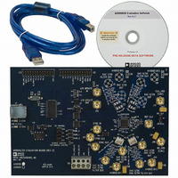
AD9958/PCB
Description
BOARD EVALUATION FOR AD9958
Manufacturer
Analog Devices Inc
Datasheet
1.AD9958BCPZ.pdf
(44 pages)
Specifications of AD9958/PCB
Design Resources
Low Jitter Sampling Clock Generator for High Performance ADCs Using AD9958/9858 and AD9515 (CN0109) Phase Coherent FSK Modulator (CN0186)
Lead Free Status / RoHS Status
Contains lead / RoHS non-compliant
Available stocks
Company
Part Number
Manufacturer
Quantity
Price
Company:

Part Number:
AD9958/PCBZ
Manufacturer:
Analog Devices Inc
Quantity:
135


AD9958
OUTPUT AMPLITUDE CONTROL MODE
The 10-bit scale factor (multiplier) controls the ramp-up and
ramp-down (RU/RD) time of an on/off emission from the DAC.
In burst transmissions of digital data, it reduces the adverse
spectral impact of abrupt bursts of data. The multiplier can
be bypassed by clearing the amplitude multiplier enable bit
(ACR[12] = 0).
Automatic and manual RU/RD modes are supported. The auto-
matic mode generates a zero-scale up to a full-scale (10 bits)
linear ramp at a rate determined by ACR (Register 0x06). The
start and direction of the ramp can be controlled by either the
profile pins or the SDIO_1/SDIO_2/SDIO_3 pins.
Manual mode allows the user to directly control the output
amplitude by manually writing to the amplitude scale factor
value in the ACR (Register 0x06). Manual mode is enabled by
setting ACR[12] = 1 and ACR[11] = 0.
Automatic RU/RD Mode Operation
Automatic RU/RD mode is active when both ACR[12] and
ACR[11] are set. When automatic RU/RD is enabled, the scale
factor is internally generated and applied to the multiplier input
port for scaling the output. The scale factor is the output of a 10-bit
counter that increments/decrements at a rate set by the 8-bit
output ramp rate register. The scale factor increments if the
external pin is high and decrements if the pin is low. The inter-
nally generated scale factor step size is controlled by ACR[15:14].
Table 21 describes the increment/decrement step size of the
internally generated scale factor per ACR[15:14].
Table 21. Increment/Decrement Step Size Assignments
Increment/Decrement Step Size
(ACR [15:14])
00
01
10
11
Table 23. Channel Assignments of SDIO_1/SDIO_2/SDIO_3 Pins for RU/RD Operation
Linear Sweep and RU/RD Modes Enabled
Simultaneously
Enable for CH0
Enable for CH0
Enable for CH1
Enable for CH1
Size
1
2
4
8
1
1
1
1
SDIO_1
Rev. A | Page 28 of 44
SDIO_2
0
0
1
1
SDIO_3
0
1
0
1
A special feature of this mode is that the maximum output
amplitude allowed is limited by the contents of the amplitude
scale factor (ACR[9:0]). This allows the user to ramp to a value
less than full scale.
Ramp Rate Timer
The ramp rate timer is a loadable down counter that generates
the clock signal to the 10-bit counter that generates the internal
scale factor. The ramp rate timer is loaded with the value of the
LSRR (Register 0x07) each time the counter reaches 1 (decimal).
This load and countdown operation continues for as long as the
timer is enabled unless the timer is forced to load before
reaching a count of 1.
If the load ARR at I/O_UPDATE bit (ACR[10]) is set, the ramp
rate timer is loaded at an I/O update, a change in profile input,
or upon reaching a value of 1. The ramp timer can be loaded
before reaching a count of 1 by three methods.
•
•
•
RU/RD Pin-to-Channel Assignment
When all four channels are in single-tone mode, the profile pins
are used for RU/RD operation.
When linear sweep and RU/RD are activated, the SDIO_1/
SDIO_2/SDIO_3 pins are used for RU/RD operation.
In modulation mode, refer to the Modulation Mode section for
pin assignments.
Table 22. Profile Pin Assignments for RU/RD Operation
Profile Pin
P2
P3
In the first method, the profile pins or the SDIO_1/
SDIO_2/SDIO_3 pins are changed. When the control
signal changes state, the ACR value is loaded into the ramp
rate timer, which then proceeds to count down as normal.
In the second method, the load ARR at I/O_UPDATE bit
(ACR[10]) is set, and an I/O update is issued.
The third method is to change from inactive automatic
RU/RD mode to active automatic RU/RD mode.
Ramp-Up/Ramp-Down Control Signal Assignment
Ramp-up function for CH0
Ramp-down function for CH0
Ramp-up function for CH1
Ramp-down function for CH1
RU/RD Operation
CH0
CH1
Related parts for AD9958/PCB
Image
Part Number
Description
Manufacturer
Datasheet
Request
R

Part Number:
Description:
BOARD EVALUATION FOR AD9958
Manufacturer:
Analog Devices Inc
Datasheet:


Part Number:
Description:
±1.7g Dual-Axis IMEMS Accelerometer Evaluation Board
Manufacturer:
Analog Devices Inc
Datasheet:

Part Number:
Description:
Inertial Sensor Evaluation System
Manufacturer:
Analog Devices Inc
Datasheet:
Part Number:
Description:
Manufacturer:
Analog Devices Inc
Datasheet:
Part Number:
Description:
Manufacturer:
Analog Devices Inc
Datasheet:
Part Number:
Description:
Manufacturer:
Analog Devices Inc
Datasheet:
Part Number:
Description:
Manufacturer:
Analog Devices Inc
Datasheet:
Part Number:
Description:
Manufacturer:
Analog Devices Inc
Datasheet:
Part Number:
Description:
Manufacturer:
Analog Devices Inc
Datasheet:
Part Number:
Description:
Manufacturer:
Analog Devices Inc
Datasheet:
Part Number:
Description:
Manufacturer:
Analog Devices Inc
Datasheet:
Part Number:
Description:
Manufacturer:
Analog Devices Inc
Datasheet: