AD9958/PCB Analog Devices Inc, AD9958/PCB Datasheet - Page 42
AD9958/PCB
Manufacturer Part Number
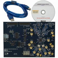
AD9958/PCB
Description
BOARD EVALUATION FOR AD9958
Manufacturer
Analog Devices Inc
Datasheet
1.AD9958BCPZ.pdf
(44 pages)
Specifications of AD9958/PCB
Design Resources
Low Jitter Sampling Clock Generator for High Performance ADCs Using AD9958/9858 and AD9515 (CN0109) Phase Coherent FSK Modulator (CN0186)
Lead Free Status / RoHS Status
Contains lead / RoHS non-compliant
Available stocks
Company
Part Number
Manufacturer
Quantity
Price
Company:

Part Number:
AD9958/PCBZ
Manufacturer:
Analog Devices Inc
Quantity:
135


AD9958
Channel Frequency Tuning Word 0 (CFTW0)—Address 0x04
Four bytes are assigned to this register.
Table 35. Description for CFTW0
Bit
31:0
Channel Phase Offset Word 0 (CPOW0)—Address 0x05
Two bytes are assigned to this register.
Table 36. Description for CPOW0
Bit
15:14
13:0
Amplitude Control Register (ACR)—Address 0x06
Three bytes are assigned to this register.
Table 37. Description for ACR
Bit
23:16
15:14
13
12
11
10
9:0
Mnemonic
Frequency Tuning Word 0
Mnemonic
Open
Phase Offset Word 0
Mnemonic
Amplitude ramp rate
Increment/decrement
step size
Open
Amplitude multiplier
enable
Ramp-up/ramp-down
enable
Load ARR at
I/O_UPDATE
Amplitude scale factor
Description
Amplitude ramp rate value.
Amplitude increment/decrement step size.
0 = amplitude multiplier is disabled. The clocks to this scaling function (auto RU/RD) are stopped
for power saving, and the data from the DDS core is routed around the multipliers (default).
1 = amplitude multiplier is enabled.
This bit is valid only when ACR[12] is active high.
0 = when ACR[12] is active, Logic 0 on ACR[11] enables the manual RU/RD operation. See the
Output Amplitude Control Mode section for details (default).
1 = if ACR[12] is active, a Logic 1 on ACR[11] enables the auto RU/RD operation. See the Output
Amplitude Control Mode section for details.
0 = the amplitude ramp rate timer is loaded only upon timeout (timer = 1) and is not loaded due
to an I/O_UPDATE input signal (default).
1 = the amplitude ramp rate timer is loaded upon timeout (timer = 1) or at the time of an
I/O_UPDATE input signal.
Amplitude scale factor for each channel.
Description
Frequency Tuning Word 0 for each channel.
Description
Phase Offset Word 0 for each channel.
Rev. A | Page 42 of 44
Related parts for AD9958/PCB
Image
Part Number
Description
Manufacturer
Datasheet
Request
R

Part Number:
Description:
BOARD EVALUATION FOR AD9958
Manufacturer:
Analog Devices Inc
Datasheet:


Part Number:
Description:
±1.7g Dual-Axis IMEMS Accelerometer Evaluation Board
Manufacturer:
Analog Devices Inc
Datasheet:

Part Number:
Description:
Inertial Sensor Evaluation System
Manufacturer:
Analog Devices Inc
Datasheet:
Part Number:
Description:
Manufacturer:
Analog Devices Inc
Datasheet:
Part Number:
Description:
Manufacturer:
Analog Devices Inc
Datasheet:
Part Number:
Description:
Manufacturer:
Analog Devices Inc
Datasheet:
Part Number:
Description:
Manufacturer:
Analog Devices Inc
Datasheet:
Part Number:
Description:
Manufacturer:
Analog Devices Inc
Datasheet:
Part Number:
Description:
Manufacturer:
Analog Devices Inc
Datasheet:
Part Number:
Description:
Manufacturer:
Analog Devices Inc
Datasheet:
Part Number:
Description:
Manufacturer:
Analog Devices Inc
Datasheet:
Part Number:
Description:
Manufacturer:
Analog Devices Inc
Datasheet: