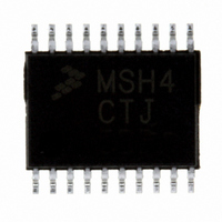
MC9S08SH4CTJ Freescale Semiconductor, MC9S08SH4CTJ Datasheet - Page 72

MC9S08SH4CTJ
Manufacturer Part Number
MC9S08SH4CTJ
Description
IC MCU 8BIT 4K FLASH 20-TSSOP
Manufacturer
Freescale Semiconductor
Series
HCS08r
Datasheet
1.MC9S08SH4CTJ.pdf
(338 pages)
Specifications of MC9S08SH4CTJ
Core Processor
HCS08
Core Size
8-Bit
Speed
40MHz
Connectivity
I²C, LIN, SCI, SPI
Peripherals
LVD, POR, PWM, WDT
Number Of I /o
17
Program Memory Size
4KB (4K x 8)
Program Memory Type
FLASH
Ram Size
256 x 8
Voltage - Supply (vcc/vdd)
2.7 V ~ 5.5 V
Data Converters
A/D 12x10b
Oscillator Type
Internal
Operating Temperature
-40°C ~ 85°C
Package / Case
20-TSSOP
Processor Series
S08SH
Core
HCS08
Data Bus Width
8 bit
Data Ram Size
256 B
Interface Type
SCI/SPI
Maximum Clock Frequency
40 MHz
Number Of Programmable I/os
17
Number Of Timers
3
Operating Supply Voltage
2.7 V to 5.5 V
Maximum Operating Temperature
+ 85 C
Mounting Style
SMD/SMT
3rd Party Development Tools
EWS08
Development Tools By Supplier
DEMO9S08SG32, DEMO9S08SG32AUTO, DEMO9S08SG8, DEMO9S08SG8AUTO, DEMO9S08SH32, DEMO9S08SH8
Minimum Operating Temperature
- 40 C
On-chip Adc
12-ch x 10-bit
A/d Bit Size
10 bit
A/d Channels Available
12
Height
1.05 mm
Length
6.6 mm
Supply Voltage (max)
5.5 V
Supply Voltage (min)
2.7 V
Width
4.5 mm
Lead Free Status / RoHS Status
Lead free / RoHS Compliant
Eeprom Size
-
Lead Free Status / Rohs Status
Lead free / RoHS Compliant
Available stocks
Company
Part Number
Manufacturer
Quantity
Price
Part Number:
MC9S08SH4CTJR
Manufacturer:
FREESCALE
Quantity:
20 000
- Current page: 72 of 338
- Download datasheet (4Mb)
1
Chapter 5 Resets, Interrupts, and General System Control
5.7.7
This high page register contains status and control bits to support the low voltage detect function, and to
enable the bandgap voltage reference for use by the ADC module.
72
LVWF will be set in the case when V
Reset:
LVWACK
LVDRE
LVDSE
LVWIE
BGBE
LVWF
LVDE
Field
7
6
5
4
3
2
0
W
R
LVWF
System Power Management Status and Control 1 Register
(SPMSC1)
Low-Voltage Warning Flag — The LVWF bit indicates the low voltage warning status.
0 Low voltage warning is not present.
1 Low voltage warning is present or was present.
Low-Voltage Warning Acknowledge — The LVWF bit indicates the low voltage warning status.Writing a 1 to
LVWACK clears LVWF to a 0 if a low voltage warning is not present.
Low-Voltage Warning Interrupt Enable — This bit enables hardware interrupt requests for LVWF.
0 Hardware interrupt disabled (use polling).
1 Request a hardware interrupt when LVWF = 1.
Low-Voltage Detect Reset Enable — This write-once bit enables LVD events to generate a hardware reset
(provided LVDE = 1).
0 LVD events do not generate hardware resets.
1 Force an MCU reset when an enabled low-voltage detect event occurs.
Low-Voltage Detect Stop Enable — Provided LVDE = 1, this control bit determines whether the low-voltage
detect function operates when the MCU is in stop mode.
0 Low-voltage detect disabled during stop mode.
1 Low-voltage detect enabled during stop mode.
Low-Voltage Detect Enable — This write-once bit enables low-voltage detect logic and qualifies the operation
of other bits in this register.
0 LVD logic disabled.
1 LVD logic enabled.
Bandgap Buffer Enable — This bit enables an internal buffer for the bandgap voltage reference for use by the
ADC module on one of its internal channels or ACMP on its ACMP+ input.
0 Bandgap buffer disabled.
1 Bandgap buffer enabled.
Figure 5-9. System Power Management Status and Control 1 Register (SPMSC1)
0
7
1
= Unimplemented or Reserved
LVWACK
0
0
6
Table 5-10. SPMSC1 Register Field Descriptions
Supply
MC9S08SH8 MCU Series Data Sheet, Rev. 3
LVWIE
transitions below the trip point or after reset and V
0
5
LVDRE
1
4
Description
LVDSE
3
1
LVDE
1
2
Supply
is already below V
Freescale Semiconductor
0
0
1
BGBE
LVW
0
0
Related parts for MC9S08SH4CTJ
Image
Part Number
Description
Manufacturer
Datasheet
Request
R
Part Number:
Description:
Manufacturer:
Freescale Semiconductor, Inc
Datasheet:
Part Number:
Description:
Manufacturer:
Freescale Semiconductor, Inc
Datasheet:
Part Number:
Description:
Manufacturer:
Freescale Semiconductor, Inc
Datasheet:
Part Number:
Description:
Manufacturer:
Freescale Semiconductor, Inc
Datasheet:
Part Number:
Description:
Manufacturer:
Freescale Semiconductor, Inc
Datasheet:
Part Number:
Description:
Manufacturer:
Freescale Semiconductor, Inc
Datasheet:
Part Number:
Description:
Manufacturer:
Freescale Semiconductor, Inc
Datasheet:
Part Number:
Description:
Manufacturer:
Freescale Semiconductor, Inc
Datasheet:
Part Number:
Description:
Manufacturer:
Freescale Semiconductor, Inc
Datasheet:
Part Number:
Description:
Manufacturer:
Freescale Semiconductor, Inc
Datasheet:
Part Number:
Description:
Manufacturer:
Freescale Semiconductor, Inc
Datasheet:
Part Number:
Description:
Manufacturer:
Freescale Semiconductor, Inc
Datasheet:
Part Number:
Description:
Manufacturer:
Freescale Semiconductor, Inc
Datasheet:
Part Number:
Description:
Manufacturer:
Freescale Semiconductor, Inc
Datasheet:
Part Number:
Description:
Manufacturer:
Freescale Semiconductor, Inc
Datasheet:


