MC9S08DZ60ACLF Freescale Semiconductor, MC9S08DZ60ACLF Datasheet - Page 148
MC9S08DZ60ACLF
Manufacturer Part Number
MC9S08DZ60ACLF
Description
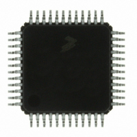
IC MCU 60K FLASH 4K RAM 48-LQFP
Manufacturer
Freescale Semiconductor
Series
HCS08r
Datasheets
1.DEMO9S08DZ60.pdf
(416 pages)
2.EVB9S08DZ60.pdf
(4 pages)
3.MC9S08DZ48AMLF.pdf
(458 pages)
Specifications of MC9S08DZ60ACLF
Core Processor
HCS08
Core Size
8-Bit
Speed
40MHz
Connectivity
CAN, I²C, LIN, SCI, SPI
Peripherals
LVD, POR, PWM, WDT
Number Of I /o
39
Program Memory Size
60KB (60K x 8)
Program Memory Type
FLASH
Eeprom Size
2K x 8
Ram Size
4K x 8
Voltage - Supply (vcc/vdd)
2.7 V ~ 5.5 V
Data Converters
A/D 16x12b
Oscillator Type
External
Operating Temperature
-40°C ~ 85°C
Package / Case
48-LQFP
Processor Series
S08DZ
Core
HCS08
Data Bus Width
8 bit
Data Ram Size
4 KB
Interface Type
CAN, I2C, SCI, SPI
Maximum Clock Frequency
40 MHz
Number Of Programmable I/os
53
Number Of Timers
2
Operating Supply Voltage
5.5 V
Maximum Operating Temperature
+ 85 C
Mounting Style
SMD/SMT
3rd Party Development Tools
EWS08
Development Tools By Supplier
DEMO9S08DZ60
Minimum Operating Temperature
- 40 C
On-chip Adc
12 bit, 24 Channel
For Use With
DEMO9S08DZ60 - BOARD DEMOEVB9S08DZ60 - BOARD EVAL FOR 9S08DZ60
Lead Free Status / RoHS Status
Lead free / RoHS Compliant
Available stocks
Company
Part Number
Manufacturer
Quantity
Price
Company:

Part Number:
MC9S08DZ60ACLF
Manufacturer:
FREESCAL
Quantity:
1 250
Company:
Part Number:
MC9S08DZ60ACLF
Manufacturer:
Freescale Semiconductor
Quantity:
10 000


Chapter 8 Multi-Purpose Clock Generator (S08MCGV1)
In FLL bypassed internal mode, the MCGOUT clock is derived from the internal reference clock. The FLL
clock is controlled by the internal reference clock, and the FLL clock frequency locks to 1024 times the
reference frequency, as selected by the RDIV bits. The MCGLCLK is derived from the FLL and the PLL
is disabled in a low power state.
8.4.1.4
In FLL bypassed external (FBE) mode, the MCGOUT clock is derived from the external reference clock
and the FLL is operational but its output clock is not used. This mode is useful to allow the FLL to acquire
its target frequency while the MCGOUT clock is driven from the external reference clock.
The FLL bypassed external mode is entered when all the following conditions occur:
In FLL bypassed external mode, the MCGOUT clock is derived from the external reference clock. The
external reference clock which is enabled can be an external crystal/resonator or it can be another external
clock source.The FLL clock is controlled by the external reference clock, and the FLL clock frequency
locks to 1024 times the reference frequency, as selected by the RDIV bits. The MCGLCLK is derived from
the FLL and the PLL is disabled in a low power state.
8.4.1.5
The PLL engaged external (PEE) mode is entered when all the following conditions occur:
In PLL engaged external mode, the MCGOUT clock is derived from the PLL clock which is controlled by
the external reference clock. The external reference clock which is enabled can be an external
crystal/resonator or it can be another external clock source The PLL clock frequency locks to a
148
•
•
•
•
•
•
•
•
•
•
LP bit is written to 0
CLKS bits are written to 10
IREFS bit is written to 0
PLLS bit is written to 0
RDIV bits are written to divide reference clock to be within the range of 31.25 kHz to 39.0625 kHz
LP bit is written to 0
CLKS bits are written to 00
IREFS bit is written to 0
PLLS bit is written to 1
RDIV bits are written to divide reference clock to be within the range of 1 MHz to 2 MHz
FLL Bypassed External (FBE)
PLL Engaged External (PEE)
It is possible to briefly operate in FBE mode with an FLL reference clock
frequency that is greater than the specified maximum frequency. This can be
necessary in applications that operate in PEE mode using an external crystal
with a frequency above 5 MHz. Please see
from FEI to PEE Mode: External Crystal = 8 MHz, Bus Frequency = 8 MHz
for a detailed example.
MC9S08DZ60 Series Data Sheet, Rev. 4
NOTE
8.5.2.4, “Example # 4: Moving
Freescale Semiconductor
Related parts for MC9S08DZ60ACLF
Image
Part Number
Description
Manufacturer
Datasheet
Request
R

Part Number:
Description:
Manufacturer:
Freescale Semiconductor, Inc
Datasheet:
Part Number:
Description:
Manufacturer:
Freescale Semiconductor, Inc
Datasheet:
Part Number:
Description:
Manufacturer:
Freescale Semiconductor, Inc
Datasheet:
Part Number:
Description:
Manufacturer:
Freescale Semiconductor, Inc
Datasheet:
Part Number:
Description:
Manufacturer:
Freescale Semiconductor, Inc
Datasheet:
Part Number:
Description:
Manufacturer:
Freescale Semiconductor, Inc
Datasheet:
Part Number:
Description:
Manufacturer:
Freescale Semiconductor, Inc
Datasheet:
Part Number:
Description:
Manufacturer:
Freescale Semiconductor, Inc
Datasheet:
Part Number:
Description:
Manufacturer:
Freescale Semiconductor, Inc
Datasheet:
Part Number:
Description:
Manufacturer:
Freescale Semiconductor, Inc
Datasheet:
Part Number:
Description:
Manufacturer:
Freescale Semiconductor, Inc
Datasheet:
Part Number:
Description:
Manufacturer:
Freescale Semiconductor, Inc
Datasheet:
Part Number:
Description:
Manufacturer:
Freescale Semiconductor, Inc
Datasheet:
Part Number:
Description:
Manufacturer:
Freescale Semiconductor, Inc
Datasheet:
Part Number:
Description:
Manufacturer:
Freescale Semiconductor, Inc
Datasheet: