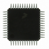
MC9S08DZ60ACLF Freescale Semiconductor, MC9S08DZ60ACLF Datasheet - Page 216

MC9S08DZ60ACLF
Manufacturer Part Number
MC9S08DZ60ACLF
Description
IC MCU 60K FLASH 4K RAM 48-LQFP
Manufacturer
Freescale Semiconductor
Series
HCS08r
Datasheets
1.DEMO9S08DZ60.pdf
(416 pages)
2.EVB9S08DZ60.pdf
(4 pages)
3.MC9S08DZ48AMLF.pdf
(458 pages)
Specifications of MC9S08DZ60ACLF
Core Processor
HCS08
Core Size
8-Bit
Speed
40MHz
Connectivity
CAN, I²C, LIN, SCI, SPI
Peripherals
LVD, POR, PWM, WDT
Number Of I /o
39
Program Memory Size
60KB (60K x 8)
Program Memory Type
FLASH
Eeprom Size
2K x 8
Ram Size
4K x 8
Voltage - Supply (vcc/vdd)
2.7 V ~ 5.5 V
Data Converters
A/D 16x12b
Oscillator Type
External
Operating Temperature
-40°C ~ 85°C
Package / Case
48-LQFP
Processor Series
S08DZ
Core
HCS08
Data Bus Width
8 bit
Data Ram Size
4 KB
Interface Type
CAN, I2C, SCI, SPI
Maximum Clock Frequency
40 MHz
Number Of Programmable I/os
53
Number Of Timers
2
Operating Supply Voltage
5.5 V
Maximum Operating Temperature
+ 85 C
Mounting Style
SMD/SMT
3rd Party Development Tools
EWS08
Development Tools By Supplier
DEMO9S08DZ60
Minimum Operating Temperature
- 40 C
On-chip Adc
12 bit, 24 Channel
For Use With
DEMO9S08DZ60 - BOARD DEMOEVB9S08DZ60 - BOARD EVAL FOR 9S08DZ60
Lead Free Status / RoHS Status
Lead free / RoHS Compliant
Available stocks
Company
Part Number
Manufacturer
Quantity
Price
Company:
Part Number:
MC9S08DZ60ACLF
Manufacturer:
FREESCAL
Quantity:
1 250
Company:
Part Number:
MC9S08DZ60ACLF
Manufacturer:
Freescale Semiconductor
Quantity:
10 000
- Current page: 216 of 416
- Download datasheet (5Mb)
Chapter 11 Inter-Integrated Circuit (S08IICV2)
11.7
216
1.
2.
3.
4.
5.
1.
2.
3.
4.
5.
6.
7.
Write: IICC2
— to enable or disable general call
— to select 10-bit or 7-bit addressing mode
Write: IICA
— to set the slave address
Write: IICC1
— to enable IIC and interrupts
Initialize RAM variables (IICEN = 1 and IICIE = 1) for transmit data
Initialize RAM variables used to achieve the routine shown in
Write: IICF
— to set the IIC baud rate (example provided in this chapter)
Write: IICC1
— to enable IIC and interrupts
Initialize RAM variables (IICEN = 1 and IICIE = 1) for transmit data
Initialize RAM variables used to achieve the routine shown in
Write: IICC1
— to enable TX
Write: IICC1
— to enable MST (master mode)
Write: IICD
— with the address of the target slave. (The lsb of this byte determines whether the communication is
The routine shown in
incoming IIC message that contains the proper address begins IIC communication. For master operation,
communication must be initiated by writing to the IICD register.
Initialization/Application Information
IICC1
IICC2 GCAEN ADEXT
IICD
IICA
IICF
IICS
master receive or transmit.)
When addressed as a slave (in slave mode), the module responds to this address
Baud rate = BUSCLK / (2 x MULT x (SCL DIVIDER))
Module configuration
Module status flags
Data register; Write to transmit IIC data read to read IIC data
Address configuration
IICEN
TCF
MULT
Figure 11-12
IAAS
IICIE
BUSY
Figure 11-11. IIC Module Quick Start
MST
MC9S08DZ60 Series Data Sheet, Rev. 4
Module Initialization (Master)
0
Module Initialization (Slave)
can handle both master and slave IIC operations. For slave operation, an
Register Model
Module Use
ARBL
TX
AD[7:1]
0
DATA
TXAK
0
0
ICR
Figure 11-12
Figure 11-12
RSTA
SRW
AD10
IICIF
AD9
0
RXAK
AD8
0
0
Freescale Semiconductor
Related parts for MC9S08DZ60ACLF
Image
Part Number
Description
Manufacturer
Datasheet
Request
R
Part Number:
Description:
Manufacturer:
Freescale Semiconductor, Inc
Datasheet:
Part Number:
Description:
Manufacturer:
Freescale Semiconductor, Inc
Datasheet:
Part Number:
Description:
Manufacturer:
Freescale Semiconductor, Inc
Datasheet:
Part Number:
Description:
Manufacturer:
Freescale Semiconductor, Inc
Datasheet:
Part Number:
Description:
Manufacturer:
Freescale Semiconductor, Inc
Datasheet:
Part Number:
Description:
Manufacturer:
Freescale Semiconductor, Inc
Datasheet:
Part Number:
Description:
Manufacturer:
Freescale Semiconductor, Inc
Datasheet:
Part Number:
Description:
Manufacturer:
Freescale Semiconductor, Inc
Datasheet:
Part Number:
Description:
Manufacturer:
Freescale Semiconductor, Inc
Datasheet:
Part Number:
Description:
Manufacturer:
Freescale Semiconductor, Inc
Datasheet:
Part Number:
Description:
Manufacturer:
Freescale Semiconductor, Inc
Datasheet:
Part Number:
Description:
Manufacturer:
Freescale Semiconductor, Inc
Datasheet:
Part Number:
Description:
Manufacturer:
Freescale Semiconductor, Inc
Datasheet:
Part Number:
Description:
Manufacturer:
Freescale Semiconductor, Inc
Datasheet:
Part Number:
Description:
Manufacturer:
Freescale Semiconductor, Inc
Datasheet:


