MC9S08DZ60ACLF Freescale Semiconductor, MC9S08DZ60ACLF Datasheet - Page 197
MC9S08DZ60ACLF
Manufacturer Part Number
MC9S08DZ60ACLF
Description
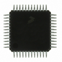
IC MCU 60K FLASH 4K RAM 48-LQFP
Manufacturer
Freescale Semiconductor
Series
HCS08r
Datasheets
1.DEMO9S08DZ60.pdf
(416 pages)
2.EVB9S08DZ60.pdf
(4 pages)
3.MC9S08DZ48AMLF.pdf
(458 pages)
Specifications of MC9S08DZ60ACLF
Core Processor
HCS08
Core Size
8-Bit
Speed
40MHz
Connectivity
CAN, I²C, LIN, SCI, SPI
Peripherals
LVD, POR, PWM, WDT
Number Of I /o
39
Program Memory Size
60KB (60K x 8)
Program Memory Type
FLASH
Eeprom Size
2K x 8
Ram Size
4K x 8
Voltage - Supply (vcc/vdd)
2.7 V ~ 5.5 V
Data Converters
A/D 16x12b
Oscillator Type
External
Operating Temperature
-40°C ~ 85°C
Package / Case
48-LQFP
Processor Series
S08DZ
Core
HCS08
Data Bus Width
8 bit
Data Ram Size
4 KB
Interface Type
CAN, I2C, SCI, SPI
Maximum Clock Frequency
40 MHz
Number Of Programmable I/os
53
Number Of Timers
2
Operating Supply Voltage
5.5 V
Maximum Operating Temperature
+ 85 C
Mounting Style
SMD/SMT
3rd Party Development Tools
EWS08
Development Tools By Supplier
DEMO9S08DZ60
Minimum Operating Temperature
- 40 C
On-chip Adc
12 bit, 24 Channel
For Use With
DEMO9S08DZ60 - BOARD DEMOEVB9S08DZ60 - BOARD EVAL FOR 9S08DZ60
Lead Free Status / RoHS Status
Lead free / RoHS Compliant
Available stocks
Company
Part Number
Manufacturer
Quantity
Price
Company:

Part Number:
MC9S08DZ60ACLF
Manufacturer:
FREESCAL
Quantity:
1 250
Company:
Part Number:
MC9S08DZ60ACLF
Manufacturer:
Freescale Semiconductor
Quantity:
10 000


10.6.2.3
System noise that occurs during the sample or conversion process can affect the accuracy of the
conversion. The ADC accuracy numbers are guaranteed as specified only if the following conditions are
met:
There are some situations where external system activity causes radiated or conducted noise emissions or
excessive V
wait or stop3 or I/O activity cannot be halted, these recommended actions may reduce the effect of noise
on the accuracy:
10.6.2.4
The ADC quantizes the ideal straight-line transfer function into 4096 steps (in 12-bit mode). Each step
ideally has the same height (1 code) and width. The width is defined as the delta between the transition
points to one code and the next. The ideal code width for an N bit converter (in this case N can be 8, 10 or
12), defined as 1
There is an inherent quantization error due to the digitization of the result. For 8-bit or 10-bit conversions
the code transitions when the voltage is at the midpoint between the points where the straight line transfer
function is exactly represented by the actual transfer function. Therefore, the quantization error will be ±
1/2 lsb in 8- or 10-bit mode. As a consequence, however, the code width of the first (0x000) conversion is
only 1/2 lsb and the code width of the last (0xFF or 0x3FF) is 1.5 lsb.
Freescale Semiconductor
•
•
•
•
•
•
•
•
•
There is a 0.1 μF low-ESR capacitor from V
There is a 0.1 μF low-ESR capacitor from V
If inductive isolation is used from the primary supply, an additional 1 μF capacitor is placed from
V
V
Operate the MCU in wait or stop3 mode before initiating (hardware triggered conversions) or
immediately after initiating (hardware or software triggered conversions) the ADC conversion.
— For software triggered conversions, immediately follow the write to ADCSC1 with a wait
— For stop3 mode operation, select ADACK as the clock source. Operation in stop3 reduces V
There is no I/O switching, input or output, on the MCU during the conversion.
Place a 0.01 μF capacitor (C
noise issues, but affects the sample rate based on the external analog source resistance).
Average the result by converting the analog input many times in succession and dividing the sum
of the results. Four samples are required to eliminate the effect of a 1
Reduce the effect of synchronous noise by operating off the asynchronous clock (ADACK) and
averaging. Noise that is synchronous to ADCK cannot be averaged out.
DDAD
SSAD
instruction or stop instruction.
noise but increases effective conversion time due to stop recovery.
DD
Noise-Induced Errors
Code Width and Quantization Error
(and V
noise is coupled into the ADC. In these situations, or when the MCU cannot be placed in
to V
LSB
SSAD
, is:
REFL
.
, if connected) is connected to V
1 lsb = (V
MC9S08DZ60 Series Data Sheet, Rev. 4
AS
) on the selected input channel to V
REFH
- V
REFL
REFH
DDAD
) / 2
to V
to V
SS
N
at a quiet point in the ground plane.
Chapter 10 Analog-to-Digital Converter (S08ADC12V1)
REFL
SSAD
.
.
REFL
LSB
or V
, one-time error.
SSAD
(this improves
Eqn. 10-2
DD
197
Related parts for MC9S08DZ60ACLF
Image
Part Number
Description
Manufacturer
Datasheet
Request
R

Part Number:
Description:
Manufacturer:
Freescale Semiconductor, Inc
Datasheet:
Part Number:
Description:
Manufacturer:
Freescale Semiconductor, Inc
Datasheet:
Part Number:
Description:
Manufacturer:
Freescale Semiconductor, Inc
Datasheet:
Part Number:
Description:
Manufacturer:
Freescale Semiconductor, Inc
Datasheet:
Part Number:
Description:
Manufacturer:
Freescale Semiconductor, Inc
Datasheet:
Part Number:
Description:
Manufacturer:
Freescale Semiconductor, Inc
Datasheet:
Part Number:
Description:
Manufacturer:
Freescale Semiconductor, Inc
Datasheet:
Part Number:
Description:
Manufacturer:
Freescale Semiconductor, Inc
Datasheet:
Part Number:
Description:
Manufacturer:
Freescale Semiconductor, Inc
Datasheet:
Part Number:
Description:
Manufacturer:
Freescale Semiconductor, Inc
Datasheet:
Part Number:
Description:
Manufacturer:
Freescale Semiconductor, Inc
Datasheet:
Part Number:
Description:
Manufacturer:
Freescale Semiconductor, Inc
Datasheet:
Part Number:
Description:
Manufacturer:
Freescale Semiconductor, Inc
Datasheet:
Part Number:
Description:
Manufacturer:
Freescale Semiconductor, Inc
Datasheet:
Part Number:
Description:
Manufacturer:
Freescale Semiconductor, Inc
Datasheet: