MC9S08DZ60ACLF Freescale Semiconductor, MC9S08DZ60ACLF Datasheet - Page 192
MC9S08DZ60ACLF
Manufacturer Part Number
MC9S08DZ60ACLF
Description
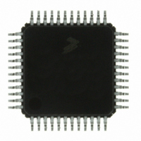
IC MCU 60K FLASH 4K RAM 48-LQFP
Manufacturer
Freescale Semiconductor
Series
HCS08r
Datasheets
1.DEMO9S08DZ60.pdf
(416 pages)
2.EVB9S08DZ60.pdf
(4 pages)
3.MC9S08DZ48AMLF.pdf
(458 pages)
Specifications of MC9S08DZ60ACLF
Core Processor
HCS08
Core Size
8-Bit
Speed
40MHz
Connectivity
CAN, I²C, LIN, SCI, SPI
Peripherals
LVD, POR, PWM, WDT
Number Of I /o
39
Program Memory Size
60KB (60K x 8)
Program Memory Type
FLASH
Eeprom Size
2K x 8
Ram Size
4K x 8
Voltage - Supply (vcc/vdd)
2.7 V ~ 5.5 V
Data Converters
A/D 16x12b
Oscillator Type
External
Operating Temperature
-40°C ~ 85°C
Package / Case
48-LQFP
Processor Series
S08DZ
Core
HCS08
Data Bus Width
8 bit
Data Ram Size
4 KB
Interface Type
CAN, I2C, SCI, SPI
Maximum Clock Frequency
40 MHz
Number Of Programmable I/os
53
Number Of Timers
2
Operating Supply Voltage
5.5 V
Maximum Operating Temperature
+ 85 C
Mounting Style
SMD/SMT
3rd Party Development Tools
EWS08
Development Tools By Supplier
DEMO9S08DZ60
Minimum Operating Temperature
- 40 C
On-chip Adc
12 bit, 24 Channel
For Use With
DEMO9S08DZ60 - BOARD DEMOEVB9S08DZ60 - BOARD EVAL FOR 9S08DZ60
Lead Free Status / RoHS Status
Lead free / RoHS Compliant
Available stocks
Company
Part Number
Manufacturer
Quantity
Price
Company:

Part Number:
MC9S08DZ60ACLF
Manufacturer:
FREESCAL
Quantity:
1 250
Company:
Part Number:
MC9S08DZ60ACLF
Manufacturer:
Freescale Semiconductor
Quantity:
10 000


Chapter 10 Analog-to-Digital Converter (S08ADC12V1)
ALTCLK for this MCU. Consult the module introduction for information on ALTCLK specific to this
MCU.
A conversion complete event sets the COCO and generates an ADC interrupt to wake the MCU from wait
mode if the ADC interrupt is enabled (AIEN = 1).
10.4.7
Stop mode is a low power-consumption standby mode during which most or all clock sources on the MCU
are disabled.
10.4.7.1
If the asynchronous clock, ADACK, is not selected as the conversion clock, executing a stop instruction
aborts the current conversion and places the ADC in its idle state. The contents of ADCRH and ADCRL
are unaffected by stop3 mode. After exiting from stop3 mode, a software or hardware trigger is required
to resume conversions.
10.4.7.2
If ADACK is selected as the conversion clock, the ADC continues operation during stop3 mode. For
guaranteed ADC operation, the MCU’s voltage regulator must remain active during stop3 mode. Consult
the module introduction for configuration information for this MCU.
If a conversion is in progress when the MCU enters stop3 mode, it continues until completion. Conversions
can be initiated while the MCU is in stop3 mode by means of the hardware trigger or if continuous
conversions are enabled.
A conversion complete event sets the COCO and generates an ADC interrupt to wake the MCU from stop3
mode if the ADC interrupt is enabled (AIEN = 1).
10.4.8
The ADC module is automatically disabled when the MCU enters stop2 mode. All module registers
contain their reset values following exit from stop2. Therefore, the module must be re-enabled and
re-configured following exit from stop2.
192
MCU Stop3 Mode Operation
MCU Stop2 Mode Operation
Stop3 Mode With ADACK Disabled
Stop3 Mode With ADACK Enabled
The ADC module can wake the system from low-power stop and cause the
MCU to begin consuming run-level currents without generating a system
level interrupt. To prevent this scenario, software should ensure the data
transfer blocking mechanism (discussed in
Conversions) is cleared when entering stop3 and continuing ADC
conversions.
MC9S08DZ60 Series Data Sheet, Rev. 4
NOTE
Section 10.4.4.2, “Completing
Freescale Semiconductor
Related parts for MC9S08DZ60ACLF
Image
Part Number
Description
Manufacturer
Datasheet
Request
R

Part Number:
Description:
Manufacturer:
Freescale Semiconductor, Inc
Datasheet:
Part Number:
Description:
Manufacturer:
Freescale Semiconductor, Inc
Datasheet:
Part Number:
Description:
Manufacturer:
Freescale Semiconductor, Inc
Datasheet:
Part Number:
Description:
Manufacturer:
Freescale Semiconductor, Inc
Datasheet:
Part Number:
Description:
Manufacturer:
Freescale Semiconductor, Inc
Datasheet:
Part Number:
Description:
Manufacturer:
Freescale Semiconductor, Inc
Datasheet:
Part Number:
Description:
Manufacturer:
Freescale Semiconductor, Inc
Datasheet:
Part Number:
Description:
Manufacturer:
Freescale Semiconductor, Inc
Datasheet:
Part Number:
Description:
Manufacturer:
Freescale Semiconductor, Inc
Datasheet:
Part Number:
Description:
Manufacturer:
Freescale Semiconductor, Inc
Datasheet:
Part Number:
Description:
Manufacturer:
Freescale Semiconductor, Inc
Datasheet:
Part Number:
Description:
Manufacturer:
Freescale Semiconductor, Inc
Datasheet:
Part Number:
Description:
Manufacturer:
Freescale Semiconductor, Inc
Datasheet:
Part Number:
Description:
Manufacturer:
Freescale Semiconductor, Inc
Datasheet:
Part Number:
Description:
Manufacturer:
Freescale Semiconductor, Inc
Datasheet: