MC9S08DZ60ACLF Freescale Semiconductor, MC9S08DZ60ACLF Datasheet - Page 400
MC9S08DZ60ACLF
Manufacturer Part Number
MC9S08DZ60ACLF
Description
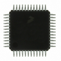
IC MCU 60K FLASH 4K RAM 48-LQFP
Manufacturer
Freescale Semiconductor
Series
HCS08r
Datasheets
1.DEMO9S08DZ60.pdf
(416 pages)
2.EVB9S08DZ60.pdf
(4 pages)
3.MC9S08DZ48AMLF.pdf
(458 pages)
Specifications of MC9S08DZ60ACLF
Core Processor
HCS08
Core Size
8-Bit
Speed
40MHz
Connectivity
CAN, I²C, LIN, SCI, SPI
Peripherals
LVD, POR, PWM, WDT
Number Of I /o
39
Program Memory Size
60KB (60K x 8)
Program Memory Type
FLASH
Eeprom Size
2K x 8
Ram Size
4K x 8
Voltage - Supply (vcc/vdd)
2.7 V ~ 5.5 V
Data Converters
A/D 16x12b
Oscillator Type
External
Operating Temperature
-40°C ~ 85°C
Package / Case
48-LQFP
Processor Series
S08DZ
Core
HCS08
Data Bus Width
8 bit
Data Ram Size
4 KB
Interface Type
CAN, I2C, SCI, SPI
Maximum Clock Frequency
40 MHz
Number Of Programmable I/os
53
Number Of Timers
2
Operating Supply Voltage
5.5 V
Maximum Operating Temperature
+ 85 C
Mounting Style
SMD/SMT
3rd Party Development Tools
EWS08
Development Tools By Supplier
DEMO9S08DZ60
Minimum Operating Temperature
- 40 C
On-chip Adc
12 bit, 24 Channel
For Use With
DEMO9S08DZ60 - BOARD DEMOEVB9S08DZ60 - BOARD EVAL FOR 9S08DZ60
Lead Free Status / RoHS Status
Lead free / RoHS Compliant
Available stocks
Company
Part Number
Manufacturer
Quantity
Price
Company:

Part Number:
MC9S08DZ60ACLF
Manufacturer:
FREESCAL
Quantity:
1 250
Company:
Part Number:
MC9S08DZ60ACLF
Manufacturer:
Freescale Semiconductor
Quantity:
10 000


Appendix B Timer Pulse-Width Modulator (TPMV2)
As an up-counter, the main 16-bit counter counts from 0x0000 through its terminal count and then
continues with 0x0000. The terminal count is 0xFFFF or a modulus value in TPMxMODH:TPMxMODL.
When center-aligned PWM operation is specified, the counter counts upward from 0x0000 through its
terminal count and then counts downward to 0x0000 where it returns to up-counting. Both 0x0000 and the
terminal count value (value in TPMxMODH:TPMxMODL) are normal length counts (one timer clock
period long).
An interrupt flag and enable are associated with the main 16-bit counter. The timer overflow flag (TOF) is
a software-accessible indication that the timer counter has overflowed. The enable signal selects between
software polling (TOIE = 0) where no hardware interrupt is generated, or interrupt-driven operation
(TOIE = 1) where a static hardware interrupt is automatically generated whenever the TOF flag is 1.
The conditions that cause TOF to become set depend on the counting mode (up or up/down). In
up-counting mode, the main 16-bit counter counts from 0x0000 through 0xFFFF and overflows to 0x0000
on the next counting clock. TOF becomes set at the transition from 0xFFFF to 0x0000. When a modulus
limit is set, TOF becomes set at the transition from the value set in the modulus register to 0x0000. When
the main 16-bit counter is operating in up-/down-counting mode, the TOF flag gets set as the counter
changes direction at the transition from the value set in the modulus register and the next lower count value.
This corresponds to the end of a PWM period. (The 0x0000 count value corresponds to the center of a
period.)
Because the HCS08 MCU is an 8-bit architecture, a coherency mechanism is built into the timer counter
for read operations. Whenever either byte of the counter is read (TPMxCNTH or TPMxCNTL), both bytes
are captured into a buffer so when the other byte is read, the value will represent the other byte of the count
at the time the first byte was read. The counter continues to count normally, but no new value can be read
from either byte until both bytes of the old count have been read.
The main timer counter can be reset manually at any time by writing any value to either byte of the timer
count TPMxCNTH or TPMxCNTL. Resetting the counter in this manner also resets the coherency
mechanism in case only one byte of the counter was read before resetting the count.
B.3.2
Channel Mode Selection
Provided CPWMS = 0 (center-aligned PWM operation is not specified), the MSnB and MSnA control bits
in the channel n status and control registers determine the basic mode of operation for the corresponding
channel. Choices include input capture, output compare, and buffered edge-aligned PWM.
B.3.2.1
Input Capture Mode
With the input capture function, the TPM can capture the time at which an external event occurs. When an
active edge occurs on the pin of an input capture channel, the TPM latches the contents of the TPM counter
into the channel value registers (TPMxCnVH:TPMxCnVL). Rising edges, falling edges, or any edge may
be chosen as the active edge that triggers an input capture.
When either byte of the 16-bit capture register is read, both bytes are latched into a buffer to support
coherent 16-bit accesses regardless of order. The coherency sequence can be manually reset by writing to
the channel status/control register (TPMxCnSC).
MC9S08DZ60 Series Data Sheet, Rev. 4
400
Freescale Semiconductor
Related parts for MC9S08DZ60ACLF
Image
Part Number
Description
Manufacturer
Datasheet
Request
R

Part Number:
Description:
Manufacturer:
Freescale Semiconductor, Inc
Datasheet:
Part Number:
Description:
Manufacturer:
Freescale Semiconductor, Inc
Datasheet:
Part Number:
Description:
Manufacturer:
Freescale Semiconductor, Inc
Datasheet:
Part Number:
Description:
Manufacturer:
Freescale Semiconductor, Inc
Datasheet:
Part Number:
Description:
Manufacturer:
Freescale Semiconductor, Inc
Datasheet:
Part Number:
Description:
Manufacturer:
Freescale Semiconductor, Inc
Datasheet:
Part Number:
Description:
Manufacturer:
Freescale Semiconductor, Inc
Datasheet:
Part Number:
Description:
Manufacturer:
Freescale Semiconductor, Inc
Datasheet:
Part Number:
Description:
Manufacturer:
Freescale Semiconductor, Inc
Datasheet:
Part Number:
Description:
Manufacturer:
Freescale Semiconductor, Inc
Datasheet:
Part Number:
Description:
Manufacturer:
Freescale Semiconductor, Inc
Datasheet:
Part Number:
Description:
Manufacturer:
Freescale Semiconductor, Inc
Datasheet:
Part Number:
Description:
Manufacturer:
Freescale Semiconductor, Inc
Datasheet:
Part Number:
Description:
Manufacturer:
Freescale Semiconductor, Inc
Datasheet:
Part Number:
Description:
Manufacturer:
Freescale Semiconductor, Inc
Datasheet: