MC908AZ60ACFUER Freescale Semiconductor, MC908AZ60ACFUER Datasheet - Page 342
MC908AZ60ACFUER
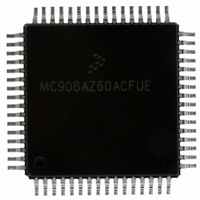
Manufacturer Part Number
MC908AZ60ACFUER
Description
IC MCU 60K FLASH 8.4MHZ 64-QFP
Manufacturer
Freescale Semiconductor
Series
HC08r
Datasheet
1.MC908AZ60ACFUER.pdf
(414 pages)
Specifications of MC908AZ60ACFUER
Core Processor
HC08
Core Size
8-Bit
Speed
8.4MHz
Connectivity
CAN, SCI, SPI
Peripherals
LVD, POR, PWM
Number Of I /o
52
Program Memory Size
60KB (60K x 8)
Program Memory Type
FLASH
Eeprom Size
1K x 8
Ram Size
2K x 8
Voltage - Supply (vcc/vdd)
4.5 V ~ 5.5 V
Data Converters
A/D 15x8b
Oscillator Type
Internal
Operating Temperature
-40°C ~ 85°C
Package / Case
64-QFP
Processor Series
HC08AZ
Core
HC08
Data Bus Width
8 bit
Data Ram Size
2 KB
Interface Type
SCI, SPI
Maximum Clock Frequency
8.4 MHz
Number Of Programmable I/os
52
Number Of Timers
8
Maximum Operating Temperature
+ 85 C
Mounting Style
SMD/SMT
Development Tools By Supplier
FSICEBASE, M68CBL05CE, ZK-HC08AX-A, M68EM08AS/AZ60AE
Minimum Operating Temperature
- 40 C
On-chip Adc
8 bit, 15 Channel
Controller Family/series
HC08
No. Of I/o's
52
Eeprom Memory Size
1KB
Ram Memory Size
2KB
Cpu Speed
8MHz
No. Of Timers
2
Rohs Compliant
Yes
Lead Free Status / RoHS Status
Lead free / RoHS Compliant
Other names
MC908AZ60ACFUERTR
Available stocks
Company
Part Number
Manufacturer
Quantity
Price
Company:

Part Number:
MC908AZ60ACFUER
Manufacturer:
FREESCALE
Quantity:
5 560
Company:
Part Number:
MC908AZ60ACFUER
Manufacturer:
Freescale Semiconductor
Quantity:
10 000


Byte Data Link Controller (BDLC)
IFR — In-Frame Response Bytes
EOF — End-of-Frame Symbol
IFS — Inter-Frame Separation Symbol
BREAK — Break
342
The IFR section of the J1850 message format is optional. Users desiring further definition of in-frame
response should review the SAE J1850 — Class B Data Communications Network Interface
specification.
This symbol is a long 280-μs passive period on the J1850 bus and is longer than an end-of-data (EOD)
symbol, which signifies the end of a message. Since an EOF symbol is longer than a 200-μs EOD
symbol, if no response is transmitted after an EOD symbol, it becomes an EOF, and the message is
assumed to be completed. The EOF flag is set upon receiving the EOF symbol.
The IFS symbol is a 20-μs passive period on the J1850 bus which allows proper synchronization
between nodes during continuous message transmission. The IFS symbol is transmitted by a node
after the completion of the end-of-frame (EOF) period and, therefore, is seen as a 300-μs passive
period.
When the last byte of a message has been transmitted onto the J1850 bus and the EOF symbol time
has expired, all nodes then must wait for the IFS symbol time to expire before transmitting a
start-of-frame (SOF) symbol, marking the beginning of another message.
However, if the BDLC is waiting for the IFS period to expire before beginning a transmission and a
rising edge is detected before the IFS time has expired, it will synchronize internally to that edge. If a
write to the BDR register (for instance, to initiate transmission) occurred on or before 104 • t
the received rising edge, then the BDLC will transmit and arbitrate for the bus. If a CPU write to the
BDR register occurred after 104 • t
transmit, but will wait for the next IFS period to expire before attempting to transmit the byte.
A rising edge may occur during the IFS period because of varying clock tolerances and loading of the
J1850 bus, causing different nodes to observe the completion of the IFS period at different times. To
allow for individual clock tolerances, receivers must synchronize to any SOF occurring during an IFS
period.
The BDLC cannot transmit a BREAK symbol.
If the BDLC is transmitting at the time a BREAK is detected, it treats the BREAK as if a transmission
error had occurred and halts transmission.
If two messages are received with a 300μs (±
(IFS) as measured at the RX pin, the start-of-frame (SOF) symbol of the
second message will generate an invalid symbol interrupt. This interrupt
results in the second message being lost and will therefore be unavailable
to the application software. Implementations of this BDLC design on silicon
have not been exposed to interframe separation rates faster than 320μs in
practical application and have therefore previously not exhibited this
behavior. Ensuring that no nodes on the J1850 network transmit messages
at 300μs (±
developing application software to robustly handle lost messages will
minimize application impact.
MC68HC908AZ60A • MC68HC908AS60A • MC68HC908AS60E Data Sheet, Rev. 6
1
μs) IFS will avoid this missed message frame. In addition,
BDLC
from the detection of the rising edge, then the BDLC will not
NOTE
1
μs) interframe separation
Freescale Semiconductor
BDLC
from
Related parts for MC908AZ60ACFUER
Image
Part Number
Description
Manufacturer
Datasheet
Request
R

Part Number:
Description:
Manufacturer:
Freescale Semiconductor, Inc
Datasheet:
Part Number:
Description:
Manufacturer:
Freescale Semiconductor, Inc
Datasheet:
Part Number:
Description:
Manufacturer:
Freescale Semiconductor, Inc
Datasheet:
Part Number:
Description:
Manufacturer:
Freescale Semiconductor, Inc
Datasheet:
Part Number:
Description:
Manufacturer:
Freescale Semiconductor, Inc
Datasheet:
Part Number:
Description:
Manufacturer:
Freescale Semiconductor, Inc
Datasheet:
Part Number:
Description:
Manufacturer:
Freescale Semiconductor, Inc
Datasheet:
Part Number:
Description:
Manufacturer:
Freescale Semiconductor, Inc
Datasheet:
Part Number:
Description:
Manufacturer:
Freescale Semiconductor, Inc
Datasheet:
Part Number:
Description:
Manufacturer:
Freescale Semiconductor, Inc
Datasheet:
Part Number:
Description:
Manufacturer:
Freescale Semiconductor, Inc
Datasheet:
Part Number:
Description:
Manufacturer:
Freescale Semiconductor, Inc
Datasheet:
Part Number:
Description:
Manufacturer:
Freescale Semiconductor, Inc
Datasheet:
Part Number:
Description:
Manufacturer:
Freescale Semiconductor, Inc
Datasheet:
Part Number:
Description:
Manufacturer:
Freescale Semiconductor, Inc
Datasheet: