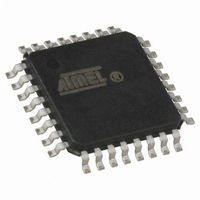
ATMEGA64M1-AU Atmel, ATMEGA64M1-AU Datasheet - Page 164

ATMEGA64M1-AU
Manufacturer Part Number
ATMEGA64M1-AU
Description
IC MCU AVR 64K FLASH 32TQFP
Manufacturer
Atmel
Series
AVR® ATmegar
Specifications of ATMEGA64M1-AU
Core Processor
AVR
Core Size
8-Bit
Speed
16MHz
Connectivity
CAN, LIN, SPI, UART/USART
Peripherals
Brown-out Detect/Reset, POR, PWM, Temp Sensor, WDT
Program Memory Size
64KB (32K x 16)
Program Memory Type
FLASH
Eeprom Size
2K x 8
Ram Size
4K x 8
Voltage - Supply (vcc/vdd)
2.7 V ~ 5.5 V
Data Converters
A/D 11x10b; D/A 1x10b
Oscillator Type
Internal
Operating Temperature
-40°C ~ 85°C
Package / Case
32-TQFP, 32-VQFP
Lead Free Status / RoHS Status
Lead free / RoHS Compliant
Number Of I /o
-
Lead Free Status / Rohs Status
Details
Available stocks
Company
Part Number
Manufacturer
Quantity
Price
- Current page: 164 of 341
- Download datasheet (6Mb)
19.3.2
19.3.2.1
Figure 19-1. CAN Standard Frames
164
Interframe
Interframe
Data Frame
Remote Frame
Space
Space
Bus Idle
Bus Idle
ATmega16M1/32M1/64M1
Message Formats
Can Standard Frame
SOF
SOF
SOF
SOF
11-bit identifier
11-bit identifier
ID10..0
ID10..0
Arbitration
Arbitration
Field
Field
ically become receivers of the message with the highest priority and do not re-attempt
transmission until the bus is available again.
The CAN protocol supports two message frame formats, the only essential difference being in
the length of the identifier. The CAN standard frame, also known as CAN 2.0 A, supports a
length of 11 bits for the identifier, and the CAN extended frame, also known as CAN 2.0 B, sup-
ports a length of 29 bits for the identifier.
A message in the CAN standard frame format begins with the "Start Of Frame (SOF)", this is fol-
lowed by the "Arbitration field" which consist of the identifier and the "Remote Transmission
Request (RTR)" bit used to distinguish between the data frame and the data request frame
called remote frame. The following "Control field" contains the "IDentifier Extension (IDE)" bit
and the "Data Length Code (DLC)" used to indicate the number of following data bytes in the
"Data field". In a remote frame, the DLC contains the number of requested data bytes. The "Data
field" that follows can hold up to 8 data bytes. The frame integrity is guaranteed by the following
"Cyclic Redundant Check (CRC)" sum. The "ACKnowledge (ACK) field" compromises the ACK
slot and the ACK delimiter. The bit in the ACK slot is sent as a recessive bit and is overwritten as
a dominant bit by the receivers which have at this time received the data correctly. Correct mes-
sages are acknowledged by the receivers regardless of the result of the acceptance test. The
end of the message is indicated by "End Of Frame (EOF)". The "Intermission Frame Space
(IFS)" is the minimum number of bits separating consecutive messages. If there is no following
bus access by any node, the bus remains idle.
RTR IDE r0
RTR IDE r0
Control
Control
Field
Field
4-bit DLC
4-bit DLC
DLC4..0
DLC4..0
15-bit CRC
CRC
Field
0 - 8 bytes
Data
Field
CRC
del.
ACK
ACK
Field
ACK
del.
End of
Frame
7 bits
15-bit CRC
CRC
Field
Intermission
3 bits
CRC
del.
Interframe
ACK
Space
ACK
Field
(Indefinite)
ACK
Bus Idle
del.
End of
Frame
7 bits
Intermission
3 bits
8209D–AVR–11/10
Interframe
Space
(Indefinite)
Bus Idle
Related parts for ATMEGA64M1-AU
Image
Part Number
Description
Manufacturer
Datasheet
Request
R

Part Number:
Description:
Manufacturer:
Atmel Corporation
Datasheet:

Part Number:
Description:
Manufacturer:
ATMEL Corporation
Datasheet:

Part Number:
Description:
Manufacturer:
ATMEL Corporation
Datasheet:

Part Number:
Description:
IC AVR MCU 64K 16MHZ 5V 64TQFP
Manufacturer:
Atmel
Datasheet:

Part Number:
Description:
IC AVR MCU 64K 16MHZ 5V 64-QFN
Manufacturer:
Atmel
Datasheet:

Part Number:
Description:
IC AVR MCU 64K 16MHZ COM 64-TQFP
Manufacturer:
Atmel
Datasheet:

Part Number:
Description:
IC AVR MCU 64K 16MHZ IND 64-TQFP
Manufacturer:
Atmel
Datasheet:

Part Number:
Description:
IC AVR MCU 64K 16MHZ COM 64-QFN
Manufacturer:
Atmel
Datasheet:

Part Number:
Description:
MCU AVR 64KB FLASH 16MHZ 64TQFP
Manufacturer:
Atmel
Datasheet:

Part Number:
Description:
MCU AVR 64KB FLASH 16MHZ 64QFN
Manufacturer:
Atmel
Datasheet:

Part Number:
Description:
IC AVR MCU 64K 16MHZ IND 64-QFN
Manufacturer:
Atmel
Datasheet:

Part Number:
Description:
IC MCU AVR 64K 5V 16MHZ 64-TQFP
Manufacturer:
Atmel
Datasheet:

Part Number:
Description:
IC MCU AVR 64K 5V 16MHZ 64-QFN
Manufacturer:
Atmel
Datasheet:

Part Number:
Description:
MCU 8-Bit ATmega AVR RISC 64KB Flash 5V 64-Pin TQFP T/R
Manufacturer:
Atmel
Datasheet:


