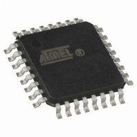
ATMEGA64M1-AU Atmel, ATMEGA64M1-AU Datasheet - Page 172

ATMEGA64M1-AU
Manufacturer Part Number
ATMEGA64M1-AU
Description
IC MCU AVR 64K FLASH 32TQFP
Manufacturer
Atmel
Series
AVR® ATmegar
Specifications of ATMEGA64M1-AU
Core Processor
AVR
Core Size
8-Bit
Speed
16MHz
Connectivity
CAN, LIN, SPI, UART/USART
Peripherals
Brown-out Detect/Reset, POR, PWM, Temp Sensor, WDT
Program Memory Size
64KB (32K x 16)
Program Memory Type
FLASH
Eeprom Size
2K x 8
Ram Size
4K x 8
Voltage - Supply (vcc/vdd)
2.7 V ~ 5.5 V
Data Converters
A/D 11x10b; D/A 1x10b
Oscillator Type
Internal
Operating Temperature
-40°C ~ 85°C
Package / Case
32-TQFP, 32-VQFP
Lead Free Status / RoHS Status
Lead free / RoHS Compliant
Number Of I /o
-
Lead Free Status / Rohs Status
Details
Available stocks
Company
Part Number
Manufacturer
Quantity
Price
- Current page: 172 of 341
- Download datasheet (6Mb)
19.5.3
19.5.4
19.5.5
19.6
172
Message Objects
ATmega16M1/32M1/64M1
Baud Rate
Fault Confinement
Overload Frame
With no baud rate prescaler (BRP[5..0]=0) the sampling point comes one time quantum too
early. This leads to a fail according the ISO16845 Test plan. It is necessary to lengthen the
Phase Segment 1 by one time quantum and to shorten the Phase Segment 2 by one time quan-
tum to compensate. The baud rate selection is made by T
Notes:
(C.f.
An overload frame is sent by setting an overload request (OVRQ). After the next reception, the
CAN channel sends an overload frame in accordance with the CAN specification. A status or
flag is set (OVRF) as long as the overload frame is sent.
Figure 19-9. Overload Frame
The MOb is a CAN frame descriptor. It contains all information to handle a CAN frame. This
means that a MOb has been outlined to allow to describe a CAN message like an object. The set
of MObs is the front end part of the “mailbox” where the messages to send and/or to receive are
pre-defined as well as possible to decrease the work load of the software.
The MObs are independent but priority is given to the lower one in case of multi matching. The
operating modes are:
1. Tsyns = 1 × Tscl = (BRP[5..0] + 1)/clk
2. Tprs = (1 to 8) × Tscl = (PRS[2..0] + 1) × Tscl
3. Tphs1 = (1 to 8) × Tscl = (PHS1[2..0] + 1) × Tscl
4. Tphs2 = (1 to 8) × Tscl = (PHS2[2..0]
5. Tsjw = (1 to 4) × Tscl = (SJW[1..0] + 1) × Tscl
Instructions
OVRQ bit
OVFG bit
RXCDAN
TXCDAN
Section 19.8 “Error Management” on page
– Disabled mode
– Transmit mode
– Receive mode
– Automatic reply
– Frame buffer receive mode
1. The total number of Tscl (Time Quanta) in a bit time must be from 8 to 25
2. PHS2[2..0] 2 is programmable to be
Tbit
(1)
= Tsyns + Tprs + Tphs1 + Tphs2
Ident "A"
Cmd
Setting OVRQ bit
Message Data "A"
(2)
IO
≤
+ 1) × Tscl
(= 1TQ)
PHS1[2..0] and
177).
CRC
A
bit
Interframe
Resetting OVRQ bit
calculation:
≥
1
Overload Frame
Overload Frame
8209D–AVR–11/10
Ident "B"
Related parts for ATMEGA64M1-AU
Image
Part Number
Description
Manufacturer
Datasheet
Request
R

Part Number:
Description:
Manufacturer:
Atmel Corporation
Datasheet:

Part Number:
Description:
Manufacturer:
ATMEL Corporation
Datasheet:

Part Number:
Description:
Manufacturer:
ATMEL Corporation
Datasheet:

Part Number:
Description:
IC AVR MCU 64K 16MHZ 5V 64TQFP
Manufacturer:
Atmel
Datasheet:

Part Number:
Description:
IC AVR MCU 64K 16MHZ 5V 64-QFN
Manufacturer:
Atmel
Datasheet:

Part Number:
Description:
IC AVR MCU 64K 16MHZ COM 64-TQFP
Manufacturer:
Atmel
Datasheet:

Part Number:
Description:
IC AVR MCU 64K 16MHZ IND 64-TQFP
Manufacturer:
Atmel
Datasheet:

Part Number:
Description:
IC AVR MCU 64K 16MHZ COM 64-QFN
Manufacturer:
Atmel
Datasheet:

Part Number:
Description:
MCU AVR 64KB FLASH 16MHZ 64TQFP
Manufacturer:
Atmel
Datasheet:

Part Number:
Description:
MCU AVR 64KB FLASH 16MHZ 64QFN
Manufacturer:
Atmel
Datasheet:

Part Number:
Description:
IC AVR MCU 64K 16MHZ IND 64-QFN
Manufacturer:
Atmel
Datasheet:

Part Number:
Description:
IC MCU AVR 64K 5V 16MHZ 64-TQFP
Manufacturer:
Atmel
Datasheet:

Part Number:
Description:
IC MCU AVR 64K 5V 16MHZ 64-QFN
Manufacturer:
Atmel
Datasheet:

Part Number:
Description:
MCU 8-Bit ATmega AVR RISC 64KB Flash 5V 64-Pin TQFP T/R
Manufacturer:
Atmel
Datasheet:


