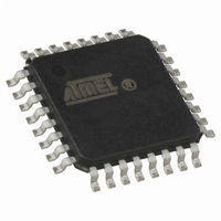
ATMEGA64M1-AU Atmel, ATMEGA64M1-AU Datasheet - Page 206

ATMEGA64M1-AU
Manufacturer Part Number
ATMEGA64M1-AU
Description
IC MCU AVR 64K FLASH 32TQFP
Manufacturer
Atmel
Series
AVR® ATmegar
Specifications of ATMEGA64M1-AU
Core Processor
AVR
Core Size
8-Bit
Speed
16MHz
Connectivity
CAN, LIN, SPI, UART/USART
Peripherals
Brown-out Detect/Reset, POR, PWM, Temp Sensor, WDT
Program Memory Size
64KB (32K x 16)
Program Memory Type
FLASH
Eeprom Size
2K x 8
Ram Size
4K x 8
Voltage - Supply (vcc/vdd)
2.7 V ~ 5.5 V
Data Converters
A/D 11x10b; D/A 1x10b
Oscillator Type
Internal
Operating Temperature
-40°C ~ 85°C
Package / Case
32-TQFP, 32-VQFP
Lead Free Status / RoHS Status
Lead free / RoHS Compliant
Number Of I /o
-
Lead Free Status / Rohs Status
Details
Available stocks
Company
Part Number
Manufacturer
Quantity
Price
- Current page: 206 of 341
- Download datasheet (6Mb)
20.5
20.5.1
20.5.2
20.5.3
20.5.4
206
LIN / UART Description
ATmega16M1/32M1/64M1
Reset
Clock
LIN Protocol Selection
Configuration
The AVR core reset logic signal also resets the LIN/UART controller. Another form of reset
exists, a software reset controlled by LSWRES bit in LINCR register. This self-reset bit performs
a partial reset as shown in
Table 20-2.
The I/O clock signal (clk
LIN13 bit in LINCR register is used to select the LIN protocol:
The controller checks the LIN13 bit in computing the checksum (enhanced checksum in LIN2.1 /
classic checksum in LIN 1.3). See
This bit is irrelevant for UART commands.
Depending on the mode (LIN or UART), LCONF[1..0] bits of the LINCR register set the controller
in the following configuration
Table 20-3.
• LIN13 = 0 (default): LIN 2.1 protocol
• LIN13 = 1: LIN 1.3 protocol
Mode
LIN
LIN Status & Interrupt Reg.
LIN Enable Interrupt Reg.
LIN Baud Rate Reg. High
LIN Data Buffer Selection
LIN Baud Rate Reg. Low
LIN Data Length Reg.
LIN Bit Timing Reg.
LIN Identifier Reg.
LIN Control Reg.
LIN Error Reg.
Register
LCONF[1..0]
LIN Data
Reset of LIN/UART Registers
Configuration Table versus Mode
00
01
10
11
b
b
b
b
i/o
) also clocks the LIN/UART controller. It is its unique clock.
Table
(Table
LINBRRH
LINBRRL
LINENIR
20-2.
LINERR
LINBTR
LINDLR
LINSEL
LINDAT
LINSIR
LINIDR
LINCR
Name
“Rx & TX Response Functions” on page
20-3):
No CRC field detection or transmission
LIN standard configuration (default)
Reset Value
0000 0000
0000 0000
0000 0000
0000 0000
0010 0000
0000 0000
0000 0000
0000 0000
1000 0000
0000 0000
0000 0000
Frame_Time_Out disable
Listening mode
Configuration
b
b
b
b
b
b
b
b
b
b
b
LSWRES Value
0000 0000
0000 0000
0000 0000
0010 0000
uuuu uuuu
0000 0000
1000 0000
0000 0000
xxxx 0000
xxxx uuuu
xxxx 0000
b
b
b
b
b
b
b
b
b
b
b
204.
u=unchanged
8209D–AVR–11/10
x=unknown
Comment
Related parts for ATMEGA64M1-AU
Image
Part Number
Description
Manufacturer
Datasheet
Request
R

Part Number:
Description:
Manufacturer:
Atmel Corporation
Datasheet:

Part Number:
Description:
Manufacturer:
ATMEL Corporation
Datasheet:

Part Number:
Description:
Manufacturer:
ATMEL Corporation
Datasheet:

Part Number:
Description:
IC AVR MCU 64K 16MHZ 5V 64TQFP
Manufacturer:
Atmel
Datasheet:

Part Number:
Description:
IC AVR MCU 64K 16MHZ 5V 64-QFN
Manufacturer:
Atmel
Datasheet:

Part Number:
Description:
IC AVR MCU 64K 16MHZ COM 64-TQFP
Manufacturer:
Atmel
Datasheet:

Part Number:
Description:
IC AVR MCU 64K 16MHZ IND 64-TQFP
Manufacturer:
Atmel
Datasheet:

Part Number:
Description:
IC AVR MCU 64K 16MHZ COM 64-QFN
Manufacturer:
Atmel
Datasheet:

Part Number:
Description:
MCU AVR 64KB FLASH 16MHZ 64TQFP
Manufacturer:
Atmel
Datasheet:

Part Number:
Description:
MCU AVR 64KB FLASH 16MHZ 64QFN
Manufacturer:
Atmel
Datasheet:

Part Number:
Description:
IC AVR MCU 64K 16MHZ IND 64-QFN
Manufacturer:
Atmel
Datasheet:

Part Number:
Description:
IC MCU AVR 64K 5V 16MHZ 64-TQFP
Manufacturer:
Atmel
Datasheet:

Part Number:
Description:
IC MCU AVR 64K 5V 16MHZ 64-QFN
Manufacturer:
Atmel
Datasheet:

Part Number:
Description:
MCU 8-Bit ATmega AVR RISC 64KB Flash 5V 64-Pin TQFP T/R
Manufacturer:
Atmel
Datasheet:


