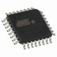
ATMEGA64M1-AU Atmel, ATMEGA64M1-AU Datasheet - Page 182

ATMEGA64M1-AU
Manufacturer Part Number
ATMEGA64M1-AU
Description
IC MCU AVR 64K FLASH 32TQFP
Manufacturer
Atmel
Series
AVR® ATmegar
Specifications of ATMEGA64M1-AU
Core Processor
AVR
Core Size
8-Bit
Speed
16MHz
Connectivity
CAN, LIN, SPI, UART/USART
Peripherals
Brown-out Detect/Reset, POR, PWM, Temp Sensor, WDT
Program Memory Size
64KB (32K x 16)
Program Memory Type
FLASH
Eeprom Size
2K x 8
Ram Size
4K x 8
Voltage - Supply (vcc/vdd)
2.7 V ~ 5.5 V
Data Converters
A/D 11x10b; D/A 1x10b
Oscillator Type
Internal
Operating Temperature
-40°C ~ 85°C
Package / Case
32-TQFP, 32-VQFP
Lead Free Status / RoHS Status
Lead free / RoHS Compliant
Number Of I /o
-
Lead Free Status / Rohs Status
Details
Available stocks
Company
Part Number
Manufacturer
Quantity
Price
- Current page: 182 of 341
- Download datasheet (6Mb)
19.10.2
182
ATmega16M1/32M1/64M1
CANGSTA – CAN General Status Register
• Bit 0 – SWRES: Software Reset Request
This auto resettable bit only resets the CAN controller.
• Bit 7 – Res: Reserved
This bit is reserved and will always read as zero.
• Bit 6 – OVRG: Overload Frame Flag
This flag does not generate an interrupt.
• Bit 5 – Res: Reserved
This bit is reserved and will always read as zero.
• Bit 4 – TXBSY: Transmitter Busy
This flag does not generate an interrupt.
• Bit 3 – RXBSY: Receiver Busy
This flag does not generate an interrupt.
Initial Value
Read/Write
– 0 - standby mode: The on-going transmission (if exists) is normally terminated and the
– 1 - enable mode: The CAN channel enters in enable mode once 11 recessive bits
– 0 - no reset
– 1 - reset: this reset is “ORed” with the hardware reset
– 0 - no overload frame
– 1 - overload frame: set by hardware as long as the produced overload frame is sent
– 0 - transmitter not busy
– 1 - transmitter busy: set by hardware as long as a frame (data, remote, overload or
– 0 - receiver not busy
– 1 - receiver busy: set by hardware as long as a frame is received or monitored
Bit
CAN channel is frozen (the CONMOB bits of every MOb do not change). The transmitter
constantly provides a recessive level. In this mode, the receiver is not enabled but all the
registers and mailbox remain accessible from CPU. In this mode, the receiver is not
enabled but all the registers and mailbox remain accessible from CPU
has been read
error frame) or an ACK field is sent. Also set when an inter frame space is sent
Note:A standby mode applied during a reception may corrupt the on-going reception or set the
controller in a wrong state. The controller will restart correctly from this state if a software
reset (SWRES) is applied. If no reset is considered, a possible solution is to wait for a lake of
a receiver busy (RXBSY) before to enter in stand-by mode. The best solution is first to apply
an abort request command (ABRQ) and then wait for the lake of the receiver busy (RXBSY)
before to enter in stand-by mode. In any cases, this standby mode behavior has no effect on
the CAN bus integrity
7
-
-
-
OVRG
R
6
0
5
-
-
-
TXBSY
R
4
0
RXBSY
R
3
0
ENFG
R
2
0
BOFF
R
1
0
ERRP
R
0
0
8209D–AVR–11/10
CANGSTA
Related parts for ATMEGA64M1-AU
Image
Part Number
Description
Manufacturer
Datasheet
Request
R

Part Number:
Description:
Manufacturer:
Atmel Corporation
Datasheet:

Part Number:
Description:
Manufacturer:
ATMEL Corporation
Datasheet:

Part Number:
Description:
Manufacturer:
ATMEL Corporation
Datasheet:

Part Number:
Description:
IC AVR MCU 64K 16MHZ 5V 64TQFP
Manufacturer:
Atmel
Datasheet:

Part Number:
Description:
IC AVR MCU 64K 16MHZ 5V 64-QFN
Manufacturer:
Atmel
Datasheet:

Part Number:
Description:
IC AVR MCU 64K 16MHZ COM 64-TQFP
Manufacturer:
Atmel
Datasheet:

Part Number:
Description:
IC AVR MCU 64K 16MHZ IND 64-TQFP
Manufacturer:
Atmel
Datasheet:

Part Number:
Description:
IC AVR MCU 64K 16MHZ COM 64-QFN
Manufacturer:
Atmel
Datasheet:

Part Number:
Description:
MCU AVR 64KB FLASH 16MHZ 64TQFP
Manufacturer:
Atmel
Datasheet:

Part Number:
Description:
MCU AVR 64KB FLASH 16MHZ 64QFN
Manufacturer:
Atmel
Datasheet:

Part Number:
Description:
IC AVR MCU 64K 16MHZ IND 64-QFN
Manufacturer:
Atmel
Datasheet:

Part Number:
Description:
IC MCU AVR 64K 5V 16MHZ 64-TQFP
Manufacturer:
Atmel
Datasheet:

Part Number:
Description:
IC MCU AVR 64K 5V 16MHZ 64-QFN
Manufacturer:
Atmel
Datasheet:

Part Number:
Description:
MCU 8-Bit ATmega AVR RISC 64KB Flash 5V 64-Pin TQFP T/R
Manufacturer:
Atmel
Datasheet:


