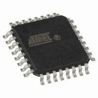
ATMEGA64M1-AU Atmel, ATMEGA64M1-AU Datasheet - Page 267

ATMEGA64M1-AU
Manufacturer Part Number
ATMEGA64M1-AU
Description
IC MCU AVR 64K FLASH 32TQFP
Manufacturer
Atmel
Series
AVR® ATmegar
Specifications of ATMEGA64M1-AU
Core Processor
AVR
Core Size
8-Bit
Speed
16MHz
Connectivity
CAN, LIN, SPI, UART/USART
Peripherals
Brown-out Detect/Reset, POR, PWM, Temp Sensor, WDT
Program Memory Size
64KB (32K x 16)
Program Memory Type
FLASH
Eeprom Size
2K x 8
Ram Size
4K x 8
Voltage - Supply (vcc/vdd)
2.7 V ~ 5.5 V
Data Converters
A/D 11x10b; D/A 1x10b
Oscillator Type
Internal
Operating Temperature
-40°C ~ 85°C
Package / Case
32-TQFP, 32-VQFP
Lead Free Status / RoHS Status
Lead free / RoHS Compliant
Number Of I /o
-
Lead Free Status / Rohs Status
Details
Available stocks
Company
Part Number
Manufacturer
Quantity
Price
- Current page: 267 of 341
- Download datasheet (6Mb)
24.5.2.1
24.5.2.2
8209D–AVR–11/10
DALA = 0
DALA = 1
To work with the 10-bit DAC, two registers have to be updated. In order to avoid intermediate
value, the DAC input values which are really converted into analog signal are buffered into
unreachable registers. In normal mode, the update of the shadow register is done when the reg-
ister DACH is written.
In case DAATE bit is set, the DAC input values will be updated on the trigger event selected
through DATS bits.
In order to avoid wrong DAC input values, the update can only be done after having written
respectively DACL and DACH registers. It is possible to work on 8-bit configuration by only writ-
ing the DACH value. In this case, update is done each trigger event.
In case DAATE bit is cleared, the DAC is in an automatic update mode. Writing the DACH regis-
ter automatically update the DAC input values with the DACH and DACL register values.
It means that whatever is the configuration of the DAATE bit, changing the DACL register has no
effect on the DAC output until the DACH register has also been updated. So, to work with 10
bits, DACL must be written first before DACH. To work with 8-bit configuration, writing DACH
allows the update of the DAC.
Bit
Read/Write
Initial Value
Bit
Read/Write
Initial Value
DAC7
DAC9
DAC1
R/W
R/W
R/W
R/W
7
0
0
7
0
0
-
DAC6
DAC8
DAC0
R/W
R/W
R/W
R/W
6
0
0
6
0
0
-
DAC5
DAC7
R/W
R/W
R/W
R/W
5
0
0
5
0
0
-
-
DAC4
DAC6
R/W
R/W
R/W
R/W
4
0
0
4
0
0
-
-
ATmega16M1/32M1/64M1
DAC3
DAC5
R/W
R/W
R/W
R/W
3
0
0
3
0
0
-
-
DAC2
DAC4
R/W
R/W
R/W
R/W
2
0
0
2
0
0
-
-
DAC9
DAC1
DAC3
R/W
R/W
R/W
R/W
1
0
0
1
0
0
-
DAC8
DAC0
DAC2
R/W
R/W
R/W
R/W
0
0
0
0
0
0
-
DACH
DACL
DACH
DACL
267
Related parts for ATMEGA64M1-AU
Image
Part Number
Description
Manufacturer
Datasheet
Request
R

Part Number:
Description:
Manufacturer:
Atmel Corporation
Datasheet:

Part Number:
Description:
Manufacturer:
ATMEL Corporation
Datasheet:

Part Number:
Description:
Manufacturer:
ATMEL Corporation
Datasheet:

Part Number:
Description:
IC AVR MCU 64K 16MHZ 5V 64TQFP
Manufacturer:
Atmel
Datasheet:

Part Number:
Description:
IC AVR MCU 64K 16MHZ 5V 64-QFN
Manufacturer:
Atmel
Datasheet:

Part Number:
Description:
IC AVR MCU 64K 16MHZ COM 64-TQFP
Manufacturer:
Atmel
Datasheet:

Part Number:
Description:
IC AVR MCU 64K 16MHZ IND 64-TQFP
Manufacturer:
Atmel
Datasheet:

Part Number:
Description:
IC AVR MCU 64K 16MHZ COM 64-QFN
Manufacturer:
Atmel
Datasheet:

Part Number:
Description:
MCU AVR 64KB FLASH 16MHZ 64TQFP
Manufacturer:
Atmel
Datasheet:

Part Number:
Description:
MCU AVR 64KB FLASH 16MHZ 64QFN
Manufacturer:
Atmel
Datasheet:

Part Number:
Description:
IC AVR MCU 64K 16MHZ IND 64-QFN
Manufacturer:
Atmel
Datasheet:

Part Number:
Description:
IC MCU AVR 64K 5V 16MHZ 64-TQFP
Manufacturer:
Atmel
Datasheet:

Part Number:
Description:
IC MCU AVR 64K 5V 16MHZ 64-QFN
Manufacturer:
Atmel
Datasheet:

Part Number:
Description:
MCU 8-Bit ATmega AVR RISC 64KB Flash 5V 64-Pin TQFP T/R
Manufacturer:
Atmel
Datasheet:


