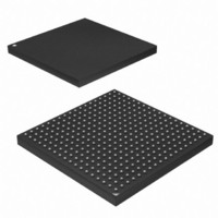
AT91SAM9G45-CU-999 Atmel, AT91SAM9G45-CU-999 Datasheet - Page 980

AT91SAM9G45-CU-999
Manufacturer Part Number
AT91SAM9G45-CU-999
Description
IC MCU ARM9 APMC 324TFBGA
Manufacturer
Atmel
Series
AT91SAMr
Datasheet
1.AT91SAM9G45-EKES.pdf
(1218 pages)
Specifications of AT91SAM9G45-CU-999
Core Processor
ARM9
Core Size
16/32-Bit
Speed
400MHz
Connectivity
EBI/EMI, Ethernet, I²C, IrDA, MMC, SPI, SSC, UART/USART, USB
Peripherals
AC'97, DMA, I²S, LCD, POR, PWM, WDT
Number Of I /o
160
Program Memory Size
64KB (64K x 8)
Program Memory Type
ROM
Ram Size
128K x 8
Voltage - Supply (vcc/vdd)
0.9 V ~ 1.1 V
Data Converters
A/D 8x10b
Oscillator Type
Internal
Operating Temperature
-40°C ~ 85°C
Package / Case
324-TFBGA
Lead Free Status / RoHS Status
Lead free / RoHS Compliant
Eeprom Size
-
Lead Free Status / Rohs Status
Supplier Unconfirmed
Available stocks
Company
Part Number
Manufacturer
Quantity
Price
- Current page: 980 of 1218
- Download datasheet (19Mb)
41.4.3.3
41.4.4
41.4.4.1
41.4.4.2
6438F–ATARM–21-Jun-10
DMAC Transfer Types
Single Transactions
Multi-buffer Transfers
Buffer Chaining Using Linked Lists
Writing a 1 to the DMAC_SREQ[2x] register starts a source single transaction request, where x
is the channel number. Writing a 1 to the DMAC_SREQ[2x+1] register starts a destination single
transfer request, where x is the channel number.
Upon completion of the chunk transaction, the hardware clears the DMAC_SREQ[x] or
DMAC_SREQ[2x+1].
Software can poll the relevant channel bit in the DMAC_CREQ[2x]/DMAC_CREQ[2x+1] and
DMAC_SREQ[x]/DMAC_SREQ[2x+1] registers. When both are 0, then either the requested
chunk or single transaction has completed.
A DMAC transfer may consist of single or multi-buffers transfers. On successive buffers of a
multi-buffer transfer, the DMAC_SADDRx/DMAC_DADDRx registers in the DMAC are repro-
grammed using either of the following methods:
On successive buffers of a multi-buffer transfer, the DMAC_CTRLAx and DMAC_CTRLBx regis-
ters in the DMAC are re-programmed using either of the following methods:
When buffer chaining, using linked lists is the multi-buffer method of choice, and on successive
buffers, the DMAC_DSCRx register in the DMAC is re-programmed using the following method:
A buffer descriptor (LLI) consists of following registers, DMAC_SADDRx, DMAC_DADDRx,
DMAC_DSCRx, DMAC_CTRLAx, DMAC_CTRLBx.These registers, along with the
DMAC_CFGx register, are used by the DMAC to set up and describe the buffer transfer.
In this case, the DMAC re-programs the channel registers prior to the start of each buffer by
fetching the buffer descriptor for that buffer from system memory. This is known as an LLI
update.
DMAC buffer chaining is supported by using a Descriptor Pointer register (DMAC_DSCRx) that
stores the address in memory of the next buffer descriptor. Each buffer descriptor contains the
corresponding buffer descriptor (DMAC_SADDRx, DMAC_DADDRx, DMAC_DSCRx,
DMAC_CTRLAx DMAC_CTRLBx).
To set up buffer chaining, a sequence of linked lists must be programmed in memory.
The DMAC_SADDRx, DMAC_DADDRx, DMAC_DSCRx, DMAC_CTRLAx and DMAC_CTRLBx
registers are fetched from system memory on an LLI update. The updated content of the
DMAC_CTRLAx register is written back to memory on buffer completion.
981
chaining.
• Buffer chaining using linked lists
• Replay mode
• Contiguous address between buffers
• Buffer chaining using linked lists
• Replay mode
• Buffer chaining using linked lists
shows how to use chained linked lists in memory to define multi-buffer transfers using buffer
AT91SAM9G45
Figure 41-5 on page
980
Related parts for AT91SAM9G45-CU-999
Image
Part Number
Description
Manufacturer
Datasheet
Request
R

Part Number:
Description:
KIT EVAL FOR AT91SAM9G45
Manufacturer:
Atmel
Datasheet:

Part Number:
Description:
MCU ARM9 324-TFBGA
Manufacturer:
Atmel
Datasheet:

Part Number:
Description:
At91 Arm Thumb-based Microcontrollers
Manufacturer:
ATMEL Corporation
Datasheet:

Part Number:
Description:
MCU, MPU & DSP Development Tools KICKSTART KIT FOR AT91SAM9 PLUS
Manufacturer:
IAR Systems

Part Number:
Description:
DEV KIT FOR AVR/AVR32
Manufacturer:
Atmel
Datasheet:

Part Number:
Description:
INTERVAL AND WIPE/WASH WIPER CONTROL IC WITH DELAY
Manufacturer:
ATMEL Corporation
Datasheet:

Part Number:
Description:
Low-Voltage Voice-Switched IC for Hands-Free Operation
Manufacturer:
ATMEL Corporation
Datasheet:

Part Number:
Description:
MONOLITHIC INTEGRATED FEATUREPHONE CIRCUIT
Manufacturer:
ATMEL Corporation
Datasheet:

Part Number:
Description:
AM-FM Receiver IC U4255BM-M
Manufacturer:
ATMEL Corporation
Datasheet:

Part Number:
Description:
Monolithic Integrated Feature Phone Circuit
Manufacturer:
ATMEL Corporation
Datasheet:

Part Number:
Description:
Multistandard Video-IF and Quasi Parallel Sound Processing
Manufacturer:
ATMEL Corporation
Datasheet:

Part Number:
Description:
High-performance EE PLD
Manufacturer:
ATMEL Corporation
Datasheet:


