DF36912GFH Renesas Electronics America, DF36912GFH Datasheet - Page 124
DF36912GFH
Manufacturer Part Number
DF36912GFH
Description
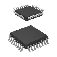
MCU 3/5V 8K 32-LQFP
Manufacturer
Renesas Electronics America
Series
H8® H8/300H Tinyr
Datasheet
1.DF36912GFHV.pdf
(442 pages)
Specifications of DF36912GFH
Core Processor
H8/300H
Core Size
16-Bit
Speed
12MHz
Connectivity
I²C, SCI
Peripherals
LVD, POR, PWM, WDT
Number Of I /o
18
Program Memory Size
8KB (8K x 8)
Program Memory Type
FLASH
Ram Size
1.5K x 8
Voltage - Supply (vcc/vdd)
3 V ~ 5.5 V
Data Converters
A/D 4x10b
Oscillator Type
Internal
Operating Temperature
-20°C ~ 75°C
Package / Case
32-LQFP
Lead Free Status / RoHS Status
Lead free / RoHS Compliant
Eeprom Size
-
Available stocks
Company
Part Number
Manufacturer
Quantity
Price
Company:

Part Number:
DF36912GFH
Manufacturer:
Renesas Electronics America
Quantity:
10 000
Company:
Part Number:
DF36912GFHV
Manufacturer:
Renesas Electronics America
Quantity:
10 000


Section 6 Power-Down Modes
6.2.3
In subsleep mode, the system clock oscillator is halted, and operation of the CPU and on-chip
peripheral modules is halted. However, as long as the rated voltage is supplied, the contents of
CPU registers, the on-chip RAM, and some on-chip peripheral module registers are retained. The
I/O ports keep the same states as before the transition.
Subsleep mode is cleared by an interrupt. When an interrupt is requested, the on-chip oscillator
starts functioning. The external oscillator also starts functioning when used. After the time set by
the STS2 to STS0 bits in SYSCR1 has elapsed, subsleep mode is cleared and the CPU starts
interrupt exception handling. Subsleep mode is not cleared if the I bit in the condition code
register (CCR) is set to 1 or the requested interrupt is disabled by the interrupt enable bit.
When the RES pin is driven low in subsleep mode, the on-chip oscillator starts functioning. The
system clock is supplied to the entire chip as soon as the on-chip oscillator starts functioning. The
RES pin must be kept low for the rated period. On driving the RES pin high, after the oscillation
stabilization time set by the power-on reset circuit has elapsed, the internal reset signal is cleared
and the CPU starts reset exception handling.
6.3
Operation in active mode is clocked at the frequency designated by the MA2 to MA0 bits in
SYSCR2. The operating frequency changes to the set frequency after SLEEP instruction
execution.
6.4
The CPU can execute programs in active mode. The operating frequency can be changed by
making a transition directly from active mode to active mode. A direct transition can be made by
executing a SLEEP instruction while the DTON bit in SYSCR2 is set to 1. If the direct transition
interrupt is disabled by the interrupt enable register 1, a transition is made instead to sleep mode or
subsleep mode. Note that if a direct transition is attempted while the I bit in condition code
register (CCR) is set to 1, sleep mode or subsleep mode will be entered though that mode cannot
be cleared by means of an interrupt.
Rev. 3.00 Sep. 14, 2006 Page 94 of 408
REJ09B0105-0300
Subsleep Mode
Operating Frequency in Active Mode
Direct Transition
Related parts for DF36912GFH
Image
Part Number
Description
Manufacturer
Datasheet
Request
R

Part Number:
Description:
Headers & Wire Housings 20P PLUG METAL COVER
Manufacturer:
Hirose Electric Co Ltd
Part Number:
Description:
Headers & Wire Housings 25P PLUG METAL COVER
Manufacturer:
Hirose Electric Co Ltd
Part Number:
Description:
Headers & Wire Housings 15P PLUG METAL COVER
Manufacturer:
Hirose Electric Co Ltd

Part Number:
Description:
0.4 Mm Pitch, 1.5 Mm Mated Height, Board-to-fine Coaxial Cable Connectors
Manufacturer:
Hirose Electric
Datasheet:
Part Number:
Description:
CONN RECEPT 40POS 0.4MM SMD GOLD
Manufacturer:
Hirose Electric Co Ltd
Datasheet:

Part Number:
Description:
KIT STARTER FOR M16C/29
Manufacturer:
Renesas Electronics America
Datasheet:

Part Number:
Description:
KIT STARTER FOR R8C/2D
Manufacturer:
Renesas Electronics America
Datasheet:

Part Number:
Description:
R0K33062P STARTER KIT
Manufacturer:
Renesas Electronics America
Datasheet:

Part Number:
Description:
KIT STARTER FOR R8C/23 E8A
Manufacturer:
Renesas Electronics America
Datasheet:

Part Number:
Description:
KIT STARTER FOR R8C/25
Manufacturer:
Renesas Electronics America
Datasheet:

Part Number:
Description:
KIT STARTER H8S2456 SHARPE DSPLY
Manufacturer:
Renesas Electronics America
Datasheet:

Part Number:
Description:
KIT STARTER FOR R8C38C
Manufacturer:
Renesas Electronics America
Datasheet:

Part Number:
Description:
KIT STARTER FOR R8C35C
Manufacturer:
Renesas Electronics America
Datasheet:

Part Number:
Description:
KIT STARTER FOR R8CL3AC+LCD APPS
Manufacturer:
Renesas Electronics America
Datasheet:
Part Number:
Description:
KIT STARTER FOR RX610
Manufacturer:
Renesas Electronics America
Datasheet: