DF36912GFH Renesas Electronics America, DF36912GFH Datasheet - Page 87
DF36912GFH
Manufacturer Part Number
DF36912GFH
Description
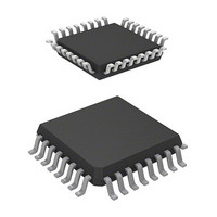
MCU 3/5V 8K 32-LQFP
Manufacturer
Renesas Electronics America
Series
H8® H8/300H Tinyr
Datasheet
1.DF36912GFHV.pdf
(442 pages)
Specifications of DF36912GFH
Core Processor
H8/300H
Core Size
16-Bit
Speed
12MHz
Connectivity
I²C, SCI
Peripherals
LVD, POR, PWM, WDT
Number Of I /o
18
Program Memory Size
8KB (8K x 8)
Program Memory Type
FLASH
Ram Size
1.5K x 8
Voltage - Supply (vcc/vdd)
3 V ~ 5.5 V
Data Converters
A/D 4x10b
Oscillator Type
Internal
Operating Temperature
-20°C ~ 75°C
Package / Case
32-LQFP
Lead Free Status / RoHS Status
Lead free / RoHS Compliant
Eeprom Size
-
Available stocks
Company
Part Number
Manufacturer
Quantity
Price
Company:

Part Number:
DF36912GFH
Manufacturer:
Renesas Electronics America
Quantity:
10 000
Company:
Part Number:
DF36912GFHV
Manufacturer:
Renesas Electronics America
Quantity:
10 000


3.4.3
Interrupts are controlled by an interrupt controller.
Interrupt operation is described as follows.
1. If an interrupt occurs while the NMI or interrupt enable bit is set to 1, an interrupt request
2. When multiple interrupt requests are generated, the interrupt controller requests to the CPU for
3. The CPU accepts the NMI or address break without depending on the I bit value. Other
4. If the CPU accepts the interrupt after processing of the current instruction is completed,
5. Then, the I bit of CCR is set to 1, masking further interrupts excluding the NMI and address
6. Next, the CPU generates the vector address corresponding to the accepted interrupt, and
signal is sent to the interrupt controller.
the interrupt handling with the highest priority at that time according to table 3.1. Other
interrupt requests are held pending.
interrupt requests are accepted, if the I bit is cleared to 0 in CCR; if the I bit is set to 1, the
interrupt request is held pending.
interrupt exception handling will begin. First, both PC and CCR are pushed onto the stack. The
state of the stack at this time is shown in figure 3.2. The PC value pushed onto the stack is the
address of the first instruction to be executed upon return from interrupt handling.
break. Upon return from interrupt handling, the values of I bit and other bits in CCR will be
restored and returned to the values prior to the start of interrupt exception handling.
transfers the address to PC as a start address of the interrupt handling-routine. Then a program
starts executing from the address indicated in PC.
Interrupt Handling Sequence
Rev. 3.00 Sep. 14, 2006 Page 57 of 408
Section 3 Exception Handling
REJ09B0105-0300
Related parts for DF36912GFH
Image
Part Number
Description
Manufacturer
Datasheet
Request
R

Part Number:
Description:
Headers & Wire Housings 20P PLUG METAL COVER
Manufacturer:
Hirose Electric Co Ltd
Part Number:
Description:
Headers & Wire Housings 25P PLUG METAL COVER
Manufacturer:
Hirose Electric Co Ltd
Part Number:
Description:
Headers & Wire Housings 15P PLUG METAL COVER
Manufacturer:
Hirose Electric Co Ltd

Part Number:
Description:
0.4 Mm Pitch, 1.5 Mm Mated Height, Board-to-fine Coaxial Cable Connectors
Manufacturer:
Hirose Electric
Datasheet:
Part Number:
Description:
CONN RECEPT 40POS 0.4MM SMD GOLD
Manufacturer:
Hirose Electric Co Ltd
Datasheet:

Part Number:
Description:
KIT STARTER FOR M16C/29
Manufacturer:
Renesas Electronics America
Datasheet:

Part Number:
Description:
KIT STARTER FOR R8C/2D
Manufacturer:
Renesas Electronics America
Datasheet:

Part Number:
Description:
R0K33062P STARTER KIT
Manufacturer:
Renesas Electronics America
Datasheet:

Part Number:
Description:
KIT STARTER FOR R8C/23 E8A
Manufacturer:
Renesas Electronics America
Datasheet:

Part Number:
Description:
KIT STARTER FOR R8C/25
Manufacturer:
Renesas Electronics America
Datasheet:

Part Number:
Description:
KIT STARTER H8S2456 SHARPE DSPLY
Manufacturer:
Renesas Electronics America
Datasheet:

Part Number:
Description:
KIT STARTER FOR R8C38C
Manufacturer:
Renesas Electronics America
Datasheet:

Part Number:
Description:
KIT STARTER FOR R8C35C
Manufacturer:
Renesas Electronics America
Datasheet:

Part Number:
Description:
KIT STARTER FOR R8CL3AC+LCD APPS
Manufacturer:
Renesas Electronics America
Datasheet:
Part Number:
Description:
KIT STARTER FOR RX610
Manufacturer:
Renesas Electronics America
Datasheet: