DF36912GFH Renesas Electronics America, DF36912GFH Datasheet - Page 25
DF36912GFH
Manufacturer Part Number
DF36912GFH
Description
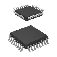
MCU 3/5V 8K 32-LQFP
Manufacturer
Renesas Electronics America
Series
H8® H8/300H Tinyr
Datasheet
1.DF36912GFHV.pdf
(442 pages)
Specifications of DF36912GFH
Core Processor
H8/300H
Core Size
16-Bit
Speed
12MHz
Connectivity
I²C, SCI
Peripherals
LVD, POR, PWM, WDT
Number Of I /o
18
Program Memory Size
8KB (8K x 8)
Program Memory Type
FLASH
Ram Size
1.5K x 8
Voltage - Supply (vcc/vdd)
3 V ~ 5.5 V
Data Converters
A/D 4x10b
Oscillator Type
Internal
Operating Temperature
-20°C ~ 75°C
Package / Case
32-LQFP
Lead Free Status / RoHS Status
Lead free / RoHS Compliant
Eeprom Size
-
Available stocks
Company
Part Number
Manufacturer
Quantity
Price
Company:

Part Number:
DF36912GFH
Manufacturer:
Renesas Electronics America
Quantity:
10 000
Company:
Part Number:
DF36912GFHV
Manufacturer:
Renesas Electronics America
Quantity:
10 000


Figure 15.8 Master Receive Mode Operation Timing (2)........................................................... 259
Figure 15.9 Slave Transmit Mode Operation Timing (1) ........................................................... 260
Figure 15.10 Slave Transmit Mode Operation Timing (2) ......................................................... 261
Figure 15.11 Slave Receive Mode Operation Timing (1)........................................................... 262
Figure 15.12 Slave Receive Mode Operation Timing (2)........................................................... 262
Figure 15.13 Clocked Synchronous Serial Transfer Format....................................................... 263
Figure 15.14 Transmit Mode Operation Timing......................................................................... 264
Figure 15.15 Receive Mode Operation Timing .......................................................................... 265
Figure 15.16 Block Diagram of Noise Canceler......................................................................... 265
Figure 15.17 Sample Flowchart for Master Transmit Mode....................................................... 266
Figure 15.18 Sample Flowchart for Master Receive Mode ........................................................ 267
Figure 15.19 Sample Flowchart for Slave Transmit Mode......................................................... 268
Figure 15.20 Sample Flowchart for Slave Receive Mode .......................................................... 269
Figure 15.21 Timing of Bit Synchronous Circuit ....................................................................... 271
Section 16 A/D Converter
Figure 16.1 Block Diagram of A/D Converter ........................................................................... 274
Figure 16.2 A/D Conversion Timing .......................................................................................... 280
Figure 16.3 External Trigger Input Timing ................................................................................ 281
Figure 16.4 A/D Conversion Accuracy Definitions (1) .............................................................. 283
Figure 16.5 A/D Conversion Accuracy Definitions (2) .............................................................. 283
Figure 16.6 Analog Input Circuit Example................................................................................. 284
Section 17 Band-Gap Circuit, Power-On Reset, and Low-Voltage Detection Circuits
Figure 17.1 Block Diagram around BGR ................................................................................... 286
Figure 17.2 Block Diagram of Power-On Reset Circuit and Low-Voltage Detection Circuit.... 287
Figure 17.3 Operational Timing of Power-On Reset Circuit...................................................... 292
Figure 17.4 Operating Timing of LVDR Circuit ........................................................................ 293
Figure 17.5 Operational Timing of LVDI Circuit....................................................................... 294
Figure 17.6 Operational Timing of LVDI Circuit
(When Compared Voltage is Input through ExtU and ExtD Pins) .......................... 296
Figure 17.7 Timing for Enabling/Disabling of Low-Voltage Detection Circuit......................... 297
Section 18 Power Supply Circuit
Figure 18.1 Power Supply Connection when Internal Step-Down Circuit is Used .................... 299
Figure 18.2 Power Supply Connection when Internal Step-Down Circuit is Not Used ............. 300
Section 20 Electrical Characteristics
Figure 20.1 System Clock Input Timing..................................................................................... 346
Figure 20.2 RES Low Width Timing.......................................................................................... 346
Figure 20.3 Input Timing............................................................................................................ 346
2
Figure 20.4 I
C Bus Interface Input/Output Timing ................................................................... 347
Rev. 3.00 Sep. 14, 2006 Page xxiii of xxviii
Related parts for DF36912GFH
Image
Part Number
Description
Manufacturer
Datasheet
Request
R

Part Number:
Description:
Headers & Wire Housings 20P PLUG METAL COVER
Manufacturer:
Hirose Electric Co Ltd
Part Number:
Description:
Headers & Wire Housings 25P PLUG METAL COVER
Manufacturer:
Hirose Electric Co Ltd
Part Number:
Description:
Headers & Wire Housings 15P PLUG METAL COVER
Manufacturer:
Hirose Electric Co Ltd

Part Number:
Description:
0.4 Mm Pitch, 1.5 Mm Mated Height, Board-to-fine Coaxial Cable Connectors
Manufacturer:
Hirose Electric
Datasheet:
Part Number:
Description:
CONN RECEPT 40POS 0.4MM SMD GOLD
Manufacturer:
Hirose Electric Co Ltd
Datasheet:

Part Number:
Description:
KIT STARTER FOR M16C/29
Manufacturer:
Renesas Electronics America
Datasheet:

Part Number:
Description:
KIT STARTER FOR R8C/2D
Manufacturer:
Renesas Electronics America
Datasheet:

Part Number:
Description:
R0K33062P STARTER KIT
Manufacturer:
Renesas Electronics America
Datasheet:

Part Number:
Description:
KIT STARTER FOR R8C/23 E8A
Manufacturer:
Renesas Electronics America
Datasheet:

Part Number:
Description:
KIT STARTER FOR R8C/25
Manufacturer:
Renesas Electronics America
Datasheet:

Part Number:
Description:
KIT STARTER H8S2456 SHARPE DSPLY
Manufacturer:
Renesas Electronics America
Datasheet:

Part Number:
Description:
KIT STARTER FOR R8C38C
Manufacturer:
Renesas Electronics America
Datasheet:

Part Number:
Description:
KIT STARTER FOR R8C35C
Manufacturer:
Renesas Electronics America
Datasheet:

Part Number:
Description:
KIT STARTER FOR R8CL3AC+LCD APPS
Manufacturer:
Renesas Electronics America
Datasheet:
Part Number:
Description:
KIT STARTER FOR RX610
Manufacturer:
Renesas Electronics America
Datasheet: