DF36912GFH Renesas Electronics America, DF36912GFH Datasheet - Page 276
DF36912GFH
Manufacturer Part Number
DF36912GFH
Description
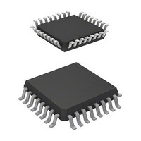
MCU 3/5V 8K 32-LQFP
Manufacturer
Renesas Electronics America
Series
H8® H8/300H Tinyr
Datasheet
1.DF36912GFHV.pdf
(442 pages)
Specifications of DF36912GFH
Core Processor
H8/300H
Core Size
16-Bit
Speed
12MHz
Connectivity
I²C, SCI
Peripherals
LVD, POR, PWM, WDT
Number Of I /o
18
Program Memory Size
8KB (8K x 8)
Program Memory Type
FLASH
Ram Size
1.5K x 8
Voltage - Supply (vcc/vdd)
3 V ~ 5.5 V
Data Converters
A/D 4x10b
Oscillator Type
Internal
Operating Temperature
-20°C ~ 75°C
Package / Case
32-LQFP
Lead Free Status / RoHS Status
Lead free / RoHS Compliant
Eeprom Size
-
Available stocks
Company
Part Number
Manufacturer
Quantity
Price
Company:

Part Number:
DF36912GFH
Manufacturer:
Renesas Electronics America
Quantity:
10 000
Company:
Part Number:
DF36912GFHV
Manufacturer:
Renesas Electronics America
Quantity:
10 000


Section 15 I
15.3.3
ICMR selects whether the MSB or LSB is transferred first, performs master mode wait control,
and selects the transfer bit count.
Rev. 3.00 Sep. 14, 2006 Page 246 of 408
REJ09B0105-0300
Bit Bit Name
3
2
1
0
Bit Bit Name
7
6
5, 4
SCLO
IICRST
MLS
WAIT
I
2
2
C Bus Mode Register (ICMR)
C Bus Interface 2 (IIC2)
Initial Value R/W Description
1
1
0
1
Initial Value R/W Description
0
0
All 1
R
R/W IIC Control Part Reset
R/W MSB-First/LSB-First Select
R/W Wait Insertion Bit
This bit monitors SCL output level. When SCLO is 1, SCL pin
outputs high. When SCLO is 0, SCL pin outputs low.
Reserved
This bit is always read as 1.
This bit resets the control part except for I
bit is set to 1 when hang-up occurs because of
communication failure during I
can be reset without setting ports and initializing registers.
Reserved
This bit is always read as 1.
0: MSB-first
1: LSB-first
Set this bit to 0 when the I
In master mode with the I
whether to insert a wait after data transfer except the
acknowledge bit. When WAIT is set to 1, after the fall of the
clock for the final data bit, low period is extended for two
transfer clocks. If WAIT is cleared to 0, data and
acknowledge bits are transferred consecutively with no wait
inserted.
The setting of this bit is invalid in slave mode with the I
format or with the clocked synchronous serial format.
Reserved
These bits are always read as 1.
2
2
C bus format, this bit selects
C bus format is used.
2
C operation, I
2
C registers. If this
2
C control part
2
C bus
Related parts for DF36912GFH
Image
Part Number
Description
Manufacturer
Datasheet
Request
R

Part Number:
Description:
Headers & Wire Housings 20P PLUG METAL COVER
Manufacturer:
Hirose Electric Co Ltd
Part Number:
Description:
Headers & Wire Housings 25P PLUG METAL COVER
Manufacturer:
Hirose Electric Co Ltd
Part Number:
Description:
Headers & Wire Housings 15P PLUG METAL COVER
Manufacturer:
Hirose Electric Co Ltd

Part Number:
Description:
0.4 Mm Pitch, 1.5 Mm Mated Height, Board-to-fine Coaxial Cable Connectors
Manufacturer:
Hirose Electric
Datasheet:
Part Number:
Description:
CONN RECEPT 40POS 0.4MM SMD GOLD
Manufacturer:
Hirose Electric Co Ltd
Datasheet:

Part Number:
Description:
KIT STARTER FOR M16C/29
Manufacturer:
Renesas Electronics America
Datasheet:

Part Number:
Description:
KIT STARTER FOR R8C/2D
Manufacturer:
Renesas Electronics America
Datasheet:

Part Number:
Description:
R0K33062P STARTER KIT
Manufacturer:
Renesas Electronics America
Datasheet:

Part Number:
Description:
KIT STARTER FOR R8C/23 E8A
Manufacturer:
Renesas Electronics America
Datasheet:

Part Number:
Description:
KIT STARTER FOR R8C/25
Manufacturer:
Renesas Electronics America
Datasheet:

Part Number:
Description:
KIT STARTER H8S2456 SHARPE DSPLY
Manufacturer:
Renesas Electronics America
Datasheet:

Part Number:
Description:
KIT STARTER FOR R8C38C
Manufacturer:
Renesas Electronics America
Datasheet:

Part Number:
Description:
KIT STARTER FOR R8C35C
Manufacturer:
Renesas Electronics America
Datasheet:

Part Number:
Description:
KIT STARTER FOR R8CL3AC+LCD APPS
Manufacturer:
Renesas Electronics America
Datasheet:
Part Number:
Description:
KIT STARTER FOR RX610
Manufacturer:
Renesas Electronics America
Datasheet: