HD6417727F100C Renesas Electronics America, HD6417727F100C Datasheet - Page 137
HD6417727F100C
Manufacturer Part Number
HD6417727F100C
Description
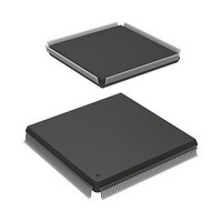
IC SUPERH MPU ROMLESS 240QFP
Manufacturer
Renesas Electronics America
Series
SuperH® SH7700r
Datasheet
1.HD6417727BP100CV.pdf
(1098 pages)
Specifications of HD6417727F100C
Core Processor
SH-3 DSP
Core Size
32-Bit
Speed
100MHz
Connectivity
FIFO, SCI, SIO, SmartCard, USB
Peripherals
DMA, LCD, POR, WDT
Number Of I /o
104
Program Memory Type
ROMless
Ram Size
32K x 8
Voltage - Supply (vcc/vdd)
1.6 V ~ 2.05 V
Data Converters
A/D 6x10b; D/A 2x8b
Oscillator Type
Internal
Operating Temperature
-20°C ~ 75°C
Package / Case
240-QFP
Lead Free Status / RoHS Status
Contains lead / RoHS non-compliant
Eeprom Size
-
Program Memory Size
-
Available stocks
Company
Part Number
Manufacturer
Quantity
Price
Company:

Part Number:
HD6417727F100C
Manufacturer:
Renesas Electronics America
Quantity:
10 000


2.6
2.6.1
The newly added instructions are classified into the following three groups:
1. Additional system control instructions for the CPU unit
2. DSP unit memory-register single and double data transfer
3. DSP unit parallel processing
Group 1 instructions are provided to support loop control and data transfer between CPU core
registers or memory and new control registers added to the CPU core. DSP operations employ a
multi-level nested-loop structure. With a single-level loop, use of the decrement and test, DTRn,
and conditional delayed branch BF/S instructions supported by the SH-3 is adequate. However,
with nested loops, DSP performance can be improved by means of a zero-overhead loop control
function.
The RS, RE, and MOD registers have been added to support loop control and modulo addressing
functions. Instructions are supported for data transfer between these new control registers and
general registers or memory. In addition, the LDRS and LDRE address calculation registers have
been added to reduce the code size for the initial settings for zero-overhead loop control.
An independent control register, DSR, is provided for the DSP engine. This register is treated as a
system register such as MACL and MACH. The A0, X0, X1, Y0, and Y1 registers are treated as
system registers from the CPU side, and LDS/STS instructions are supported for the same
purpose. Table 2.26 shows the instruction code map for the new system control instructions for the
CPU core.
Group 2 instructions are provided to reduce DSP operation program code size. Data transfer
instructions that perform no data processing are frequently executed by the DSP engine. In this
case, a 32-bit instruction code is unnecessarily long, and wastes space in the program memory
area. All instructions in this class have a 16-bit code length, the same as conventional SH core
instructions. Single data transfer instructions have greater flexibility in terms of operands than the
double data transfer instruction or parallel instruction class.
Group 3 instructions are provided for fast execution of digital signal processing operations using
the DSP unit. These instructions have a 32-bit instruction code, so that a maximum of four
instructions—an ALU operation, multiplication, and two data transfer instructions—can be
executed in parallel.
DSP Extended-Function Instructions
Introduction
Rev.6.00 Mar. 27, 2009 Page 79 of 1036
REJ09B0254-0600
Section 2 CPU
Related parts for HD6417727F100C
Image
Part Number
Description
Manufacturer
Datasheet
Request
R

Part Number:
Description:
KIT STARTER FOR M16C/29
Manufacturer:
Renesas Electronics America
Datasheet:

Part Number:
Description:
KIT STARTER FOR R8C/2D
Manufacturer:
Renesas Electronics America
Datasheet:

Part Number:
Description:
R0K33062P STARTER KIT
Manufacturer:
Renesas Electronics America
Datasheet:

Part Number:
Description:
KIT STARTER FOR R8C/23 E8A
Manufacturer:
Renesas Electronics America
Datasheet:

Part Number:
Description:
KIT STARTER FOR R8C/25
Manufacturer:
Renesas Electronics America
Datasheet:

Part Number:
Description:
KIT STARTER H8S2456 SHARPE DSPLY
Manufacturer:
Renesas Electronics America
Datasheet:

Part Number:
Description:
KIT STARTER FOR R8C38C
Manufacturer:
Renesas Electronics America
Datasheet:

Part Number:
Description:
KIT STARTER FOR R8C35C
Manufacturer:
Renesas Electronics America
Datasheet:

Part Number:
Description:
KIT STARTER FOR R8CL3AC+LCD APPS
Manufacturer:
Renesas Electronics America
Datasheet:
Part Number:
Description:
KIT STARTER FOR RX610
Manufacturer:
Renesas Electronics America
Datasheet:

Part Number:
Description:
KIT STARTER FOR R32C/118
Manufacturer:
Renesas Electronics America
Datasheet:

Part Number:
Description:
KIT DEV RSK-R8C/26-29
Manufacturer:
Renesas Electronics America
Datasheet:

Part Number:
Description:
KIT STARTER FOR SH7124
Manufacturer:
Renesas Electronics America
Datasheet:

Part Number:
Description:
KIT STARTER FOR H8SX/1622
Manufacturer:
Renesas Electronics America
Datasheet:

Part Number:
Description:
KIT DEV FOR SH7203
Manufacturer:
Renesas Electronics America
Datasheet: