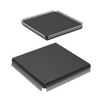
HD6417727F100C Renesas Electronics America, HD6417727F100C Datasheet - Page 23

HD6417727F100C
Manufacturer Part Number
HD6417727F100C
Description
IC SUPERH MPU ROMLESS 240QFP
Manufacturer
Renesas Electronics America
Series
SuperH® SH7700r
Datasheet
1.HD6417727BP100CV.pdf
(1098 pages)
Specifications of HD6417727F100C
Core Processor
SH-3 DSP
Core Size
32-Bit
Speed
100MHz
Connectivity
FIFO, SCI, SIO, SmartCard, USB
Peripherals
DMA, LCD, POR, WDT
Number Of I /o
104
Program Memory Type
ROMless
Ram Size
32K x 8
Voltage - Supply (vcc/vdd)
1.6 V ~ 2.05 V
Data Converters
A/D 6x10b; D/A 2x8b
Oscillator Type
Internal
Operating Temperature
-20°C ~ 75°C
Package / Case
240-QFP
Lead Free Status / RoHS Status
Contains lead / RoHS non-compliant
Eeprom Size
-
Program Memory Size
-
Available stocks
Company
Part Number
Manufacturer
Quantity
Price
Company:
Part Number:
HD6417727F100C
Manufacturer:
Renesas Electronics America
Quantity:
10 000
- Current page: 23 of 1098
- Download datasheet (7Mb)
8.3
Section 9 Power-Down Modes and Software Reset
9.1
9.2
9.3
9.4
9.5
9.6
9.7
8.2.14 Break ASID Register B (BASRB) ....................................................................... 221
Operation Description ....................................................................................................... 222
8.3.1
8.3.2
8.3.3
8.3.4
8.3.5
8.3.6
8.3.7
8.3.8
8.3.9
Overview........................................................................................................................... 233
9.1.1
9.1.2
9.1.3
Register Description.......................................................................................................... 236
9.2.1
9.2.2
9.2.3
9.2.4
Sleep Mode ....................................................................................................................... 243
9.3.1
9.3.2
Standby Mode ................................................................................................................... 243
9.4.1
9.4.2
9.4.3
Module Standby Function................................................................................................. 247
9.5.1
9.5.2
Timing of STATUS Pin Changes ..................................................................................... 249
9.6.1
9.6.2
9.6.3
Hardware Standby Mode .................................................................................................. 254
9.7.1
9.7.2
9.7.3
Flow of the User Break Operation ....................................................................... 222
Break on Instruction Fetch Cycle......................................................................... 222
Break by Data Access Cycle................................................................................ 223
Break on X/Y-Memory Bus Cycle....................................................................... 224
Sequential Break .................................................................................................. 224
Value of Saved Program Counter ........................................................................ 224
PC Trace .............................................................................................................. 225
Usage Examples................................................................................................... 227
Usage Notes ......................................................................................................... 231
Power-Down Modes ............................................................................................ 233
Pin Configuration................................................................................................. 235
Register Configuration......................................................................................... 235
Standby Control Register (STBCR)..................................................................... 236
Standby Control Register 2 (STBCR2)................................................................ 237
Standby Control Register 3 (STBCR3)................................................................ 239
Module Software Reset Register (SRSTR)......................................................... 241
Transition to Sleep Mode..................................................................................... 243
Canceling Sleep Mode ......................................................................................... 243
Transition to Standby Mode................................................................................. 243
Canceling Standby Mode ..................................................................................... 245
Clock Pause Function .......................................................................................... 246
Transition to Module Standby Function .............................................................. 247
Clearing the Module Standby Function ............................................................... 249
Timing for Resets................................................................................................. 249
Timing for Canceling Standbys ........................................................................... 250
Timing for Canceling Sleep Mode....................................................................... 252
Transition to Hardware Standby Mode ................................................................ 254
Clearing the Hardware Standby Mode................................................................. 254
Timing of Hardware Standby Mode .................................................................... 255
Rev.6.00 Mar. 27, 2009 Page xxi of lvi
.................................................. 233
REJ09B0254-0600
Related parts for HD6417727F100C
Image
Part Number
Description
Manufacturer
Datasheet
Request
R

Part Number:
Description:
KIT STARTER FOR M16C/29
Manufacturer:
Renesas Electronics America
Datasheet:

Part Number:
Description:
KIT STARTER FOR R8C/2D
Manufacturer:
Renesas Electronics America
Datasheet:

Part Number:
Description:
R0K33062P STARTER KIT
Manufacturer:
Renesas Electronics America
Datasheet:

Part Number:
Description:
KIT STARTER FOR R8C/23 E8A
Manufacturer:
Renesas Electronics America
Datasheet:

Part Number:
Description:
KIT STARTER FOR R8C/25
Manufacturer:
Renesas Electronics America
Datasheet:

Part Number:
Description:
KIT STARTER H8S2456 SHARPE DSPLY
Manufacturer:
Renesas Electronics America
Datasheet:

Part Number:
Description:
KIT STARTER FOR R8C38C
Manufacturer:
Renesas Electronics America
Datasheet:

Part Number:
Description:
KIT STARTER FOR R8C35C
Manufacturer:
Renesas Electronics America
Datasheet:

Part Number:
Description:
KIT STARTER FOR R8CL3AC+LCD APPS
Manufacturer:
Renesas Electronics America
Datasheet:

Part Number:
Description:
KIT STARTER FOR RX610
Manufacturer:
Renesas Electronics America
Datasheet:

Part Number:
Description:
KIT STARTER FOR R32C/118
Manufacturer:
Renesas Electronics America
Datasheet:

Part Number:
Description:
KIT DEV RSK-R8C/26-29
Manufacturer:
Renesas Electronics America
Datasheet:

Part Number:
Description:
KIT STARTER FOR SH7124
Manufacturer:
Renesas Electronics America
Datasheet:

Part Number:
Description:
KIT STARTER FOR H8SX/1622
Manufacturer:
Renesas Electronics America
Datasheet:

Part Number:
Description:
KIT DEV FOR SH7203
Manufacturer:
Renesas Electronics America
Datasheet:


