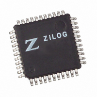
Z8F6401AN020SC00TR Zilog, Z8F6401AN020SC00TR Datasheet - Page 100

Z8F6401AN020SC00TR
Manufacturer Part Number
Z8F6401AN020SC00TR
Description
IC ENCORE MCU FLASH 64K 44LQFP
Manufacturer
Zilog
Series
Encore!®r
Datasheet
1.Z8F1601VN020EC.pdf
(246 pages)
Specifications of Z8F6401AN020SC00TR
Core Processor
Z8
Core Size
8-Bit
Speed
20MHz
Connectivity
I²C, IrDA, SPI, UART/USART
Peripherals
Brown-out Detect/Reset, DMA, POR, PWM, WDT
Number Of I /o
31
Program Memory Size
64KB (64K x 8)
Program Memory Type
FLASH
Ram Size
4K x 8
Voltage - Supply (vcc/vdd)
3 V ~ 3.6 V
Data Converters
A/D 8x10b
Oscillator Type
Internal
Operating Temperature
0°C ~ 70°C
Package / Case
44-LQFP
Lead Free Status / RoHS Status
Contains lead / RoHS non-compliant
Eeprom Size
-
Other names
Z8F6401AN020SC00T
Available stocks
Company
Part Number
Manufacturer
Quantity
Price
- Current page: 100 of 246
- Download datasheet (2Mb)
PS017610-0404
Receiving Data using the Polled Method
Receiving Data using the Interrupt-Driven Method
Follow these steps to configure the UART for polled data reception:
1. Write to the UART Baud Rate High and Low Byte registers to set the desired baud
2. Enable the UART pin functions by configuring the associated GPIO Port pins for
3. Write to the UART Control 1 register to enable Multiprocessor (9-bit) mode functions,
4. Write to the UART Control 0 register to:
5. Check the RDA bit in the UART Status 0 register to determine if the Receive Data
6. Read data from the UART Receive Data register. If operating in Multiprocessor (9-bit)
7. Return to Step 6 to receive additional data.
ditions). Follow these steps to configure the UART receiver for interrupt-driven operation:
1. Write to the UART Baud Rate High and Low Byte registers to set the desired baud
2. Enable the UART pin functions by configuring the associated GPIO Port pins for
3. Execute a DI instruction to disable interrupts.
4. Write to the Interrupt control registers to enable the UART Receiver interrupt and set
5. Clear the UART Receiver interrupt in the applicable Interrupt Request register.
6. Write to the UART Control 1 register to enable Multiprocessor (9-bit) mode functions,
The UART Receiver interrupt indicates the availability of new data (as well as error con-
rate.
alternate function operation.
if desired.
–
–
register contains a valid data byte (indicated by a 1). If RDA is set to 1 to indicate
available data, continue to Step 6. If the Receive Data register is empty (indicated by a
0), continue to monitor the RDA bit awaiting reception of the valid data.
mode, first read the Multiprocessor Receive flag (MPRX) to determine if the data was
directed to this UART before reading the data.
rate.
alternate function operation.
the desired priority.
if desired.
Set the receive enable bit (REN) to enable the UART for data reception
Enable parity, if desired, and select either even or odd parity.
Z8F640x/Z8F480x/Z8F320x/Z8F240x/Z8F160x
Z8 Encore!
UART
®
82
Related parts for Z8F6401AN020SC00TR
Image
Part Number
Description
Manufacturer
Datasheet
Request
R

Part Number:
Description:
Communication Controllers, ZILOG INTELLIGENT PERIPHERAL CONTROLLER (ZIP)
Manufacturer:
Zilog, Inc.
Datasheet:

Part Number:
Description:
KIT DEV FOR Z8 ENCORE 16K TO 64K
Manufacturer:
Zilog
Datasheet:

Part Number:
Description:
KIT DEV Z8 ENCORE XP 28-PIN
Manufacturer:
Zilog
Datasheet:

Part Number:
Description:
DEV KIT FOR Z8 ENCORE 8K/4K
Manufacturer:
Zilog
Datasheet:

Part Number:
Description:
KIT DEV Z8 ENCORE XP 28-PIN
Manufacturer:
Zilog
Datasheet:

Part Number:
Description:
DEV KIT FOR Z8 ENCORE 4K TO 8K
Manufacturer:
Zilog
Datasheet:

Part Number:
Description:
CMOS Z8 microcontroller. ROM 16 Kbytes, RAM 256 bytes, speed 16 MHz, 32 lines I/O, 3.0V to 5.5V
Manufacturer:
Zilog, Inc.
Datasheet:

Part Number:
Description:
Low-cost microcontroller. 512 bytes ROM, 61 bytes RAM, 8 MHz
Manufacturer:
Zilog, Inc.
Datasheet:

Part Number:
Description:
Z8 4K OTP Microcontroller
Manufacturer:
Zilog, Inc.
Datasheet:

Part Number:
Description:
CMOS SUPER8 ROMLESS MCU
Manufacturer:
Zilog, Inc.
Datasheet:

Part Number:
Description:
SL1866 CMOSZ8 OTP Microcontroller
Manufacturer:
Zilog, Inc.
Datasheet:

Part Number:
Description:
SL1866 CMOSZ8 OTP Microcontroller
Manufacturer:
Zilog, Inc.
Datasheet:

Part Number:
Description:
OTP (KB) = 1, RAM = 125, Speed = 12, I/O = 14, 8-bit Timers = 2, Comm Interfaces Other Features = Por, LV Protect, Voltage = 4.5-5.5V
Manufacturer:
Zilog, Inc.
Datasheet:

Part Number:
Description:
Manufacturer:
Zilog, Inc.
Datasheet:


