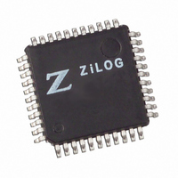
Z8F6401AN020SC00TR Zilog, Z8F6401AN020SC00TR Datasheet - Page 134

Z8F6401AN020SC00TR
Manufacturer Part Number
Z8F6401AN020SC00TR
Description
IC ENCORE MCU FLASH 64K 44LQFP
Manufacturer
Zilog
Series
Encore!®r
Datasheet
1.Z8F1601VN020EC.pdf
(246 pages)
Specifications of Z8F6401AN020SC00TR
Core Processor
Z8
Core Size
8-Bit
Speed
20MHz
Connectivity
I²C, IrDA, SPI, UART/USART
Peripherals
Brown-out Detect/Reset, DMA, POR, PWM, WDT
Number Of I /o
31
Program Memory Size
64KB (64K x 8)
Program Memory Type
FLASH
Ram Size
4K x 8
Voltage - Supply (vcc/vdd)
3 V ~ 3.6 V
Data Converters
A/D 8x10b
Oscillator Type
Internal
Operating Temperature
0°C ~ 70°C
Package / Case
44-LQFP
Lead Free Status / RoHS Status
Contains lead / RoHS non-compliant
Eeprom Size
-
Other names
Z8F6401AN020SC00T
Available stocks
Company
Part Number
Manufacturer
Quantity
Price
- Current page: 134 of 246
- Download datasheet (2Mb)
PS017609-0803
Reading a Transaction with a 10-Bit Address
1. Software writes the I
2. Software asserts the START bit of the I
3. Software asserts the NAK bit of the I
4. The I
5. The I
6. The I
7. The I
8. The I
9. Software responds by reading the I
10. The I
11. A NAK interrupt is generated by the I
12. Software responds by setting the STOP bit of the I
13. A STOP condition is sent to the I
Figure 82 illustrates the receive format for a 10-bit addressed slave. The shaded regions
indicate data transferred from the I
data transferred from the slaves to the I
Figure 82. Receive Data Format for a 10-Bit Addressed Slave
The first seven bits transmitted in the first byte are
most-significant bits of the 10-bit address. The lowest bit of the first byte transferred is the
write signal.
The data transfer format for a receive operation on a 10-bit addressed slave is as follows:
1. Software writes an address
2. Software asserts the START bit of the I
3. The I
S Slave Address
1st 7 bits
data has been read by the I
high period of SCL.
2
2
2
2
2
2
2
C Controller sends the START condition.
C Controller sends the address and read bit by the SDA signal.
C slave sends an Acknowledge by pulling the SDA signal Low during the next
C Controller reads the first byte of data from the I
C Controller asserts the Receive interrupt.
C Controller sends a NAK to the I
C Controller sends the Start condition.
W=0 A Slave address
2
C Data register with a 7-bit slave address followed by a 1 (read).
2nd Byte
2
11110B
C Controller, a Not Acknowledge is sent to the I
2
C Controller to slaves and unshaded regions indicate
Z8F640x/Z8F480x/Z8F320x/Z8F240x/Z8F160x
2
C slave.
2
2
C Data register.
C Controller.
2
followed by the two address bits and a 0 (write).
C Control register so that after the first byte of
2
A S Slave Address
C Controller.
2
2
C Control register.
C Control register.
2
C slave.
1st 7 bits
11110XX
2
C Control register.
2
. The two bits
C slave.
R=1 A Data A Data A P
XX
Z8 Encore!
I2C Controller
are the two
2
C slave.
®
116
Related parts for Z8F6401AN020SC00TR
Image
Part Number
Description
Manufacturer
Datasheet
Request
R

Part Number:
Description:
Communication Controllers, ZILOG INTELLIGENT PERIPHERAL CONTROLLER (ZIP)
Manufacturer:
Zilog, Inc.
Datasheet:

Part Number:
Description:
KIT DEV FOR Z8 ENCORE 16K TO 64K
Manufacturer:
Zilog
Datasheet:

Part Number:
Description:
KIT DEV Z8 ENCORE XP 28-PIN
Manufacturer:
Zilog
Datasheet:

Part Number:
Description:
DEV KIT FOR Z8 ENCORE 8K/4K
Manufacturer:
Zilog
Datasheet:

Part Number:
Description:
KIT DEV Z8 ENCORE XP 28-PIN
Manufacturer:
Zilog
Datasheet:

Part Number:
Description:
DEV KIT FOR Z8 ENCORE 4K TO 8K
Manufacturer:
Zilog
Datasheet:

Part Number:
Description:
CMOS Z8 microcontroller. ROM 16 Kbytes, RAM 256 bytes, speed 16 MHz, 32 lines I/O, 3.0V to 5.5V
Manufacturer:
Zilog, Inc.
Datasheet:

Part Number:
Description:
Low-cost microcontroller. 512 bytes ROM, 61 bytes RAM, 8 MHz
Manufacturer:
Zilog, Inc.
Datasheet:

Part Number:
Description:
Z8 4K OTP Microcontroller
Manufacturer:
Zilog, Inc.
Datasheet:

Part Number:
Description:
CMOS SUPER8 ROMLESS MCU
Manufacturer:
Zilog, Inc.
Datasheet:

Part Number:
Description:
SL1866 CMOSZ8 OTP Microcontroller
Manufacturer:
Zilog, Inc.
Datasheet:

Part Number:
Description:
SL1866 CMOSZ8 OTP Microcontroller
Manufacturer:
Zilog, Inc.
Datasheet:

Part Number:
Description:
OTP (KB) = 1, RAM = 125, Speed = 12, I/O = 14, 8-bit Timers = 2, Comm Interfaces Other Features = Por, LV Protect, Voltage = 4.5-5.5V
Manufacturer:
Zilog, Inc.
Datasheet:

Part Number:
Description:
Manufacturer:
Zilog, Inc.
Datasheet:


