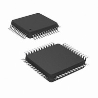
M052LAN Nuvoton Technology Corporation of America, M052LAN Datasheet - Page 165

M052LAN
Manufacturer Part Number
M052LAN
Description
IC MCU 32BIT 8KB FLASH 48LQFP
Manufacturer
Nuvoton Technology Corporation of America
Series
NuMicro M051™r
Specifications of M052LAN
Core Processor
ARM Cortex-M0
Core Size
32-Bit
Speed
50MHz
Connectivity
EBI/EMI, I²C, IrDA, SPI, UART/USART
Peripherals
Brown-out Detect/Reset, LVD, POR, PWM, WDT
Number Of I /o
40
Program Memory Size
8KB (8K x 8)
Program Memory Type
FLASH
Ram Size
4K x 8
Voltage - Supply (vcc/vdd)
2.5 V ~ 5.5 V
Data Converters
A/D 8x12b
Oscillator Type
Internal
Operating Temperature
-40°C ~ 85°C
Package / Case
48-LQFP
Lead Free Status / RoHS Status
Lead free / RoHS Compliant
Eeprom Size
-
Available stocks
Company
Part Number
Manufacturer
Quantity
Price
Company:
Part Number:
M052LAN
Manufacturer:
NuvoTon
Quantity:
130
Company:
Part Number:
M052LAN
Manufacturer:
Nuvoton Technology Corporation of America
Quantity:
10 000
Part Number:
M052LAN
Manufacturer:
NUVOTON
Quantity:
20 000
- Current page: 165 of 384
- Download datasheet (4Mb)
6.5.4.3 Control Register (I2CON)
NuMicro M051
by the I2C hardware and cannot be accessed by the CPU. Serial data is shifted through the
acknowledge bit into I2CDAT [7:0] on the rising edges of serial clock pulses on the SCL line.
When a byte has been shifted into I2CDAT [7:0], the serial data is available in I2CDAT [7:0], and
the acknowledge bit (ACK or NACK) is returned by the control logic during the ninth clock pulse.
Serial data is shifted out from I2CDAT [7:0] on the falling edges of SCL clock pulses, and is
shifted into I2CDAT [7:0] on the rising edges of SCL clock pulses.
The CPU can read from and write to this 8-bit field of I2CON [7:0] directly. Two bits are affected
by hardware: the SI bit is set when the I2C hardware requests a serial interrupt, and the STO bit
is cleared when a STOP condition is present on the bus. The STO bit is also cleared when ENS1
= ‘0’.
EI
ENSI
STA
STO
SI
AA
I2C Data Register:
I2DAT.7 I2DAT.6 I2DAT.5 I2DAT.4 I2DAT.3 I2DAT.2 I2DAT.1 I2DAT.0
Enable Interrupt.
Set to enable I2C serial function block. When ENSI=1 the I2C serial function enables.
The Multi Function pin function of SDA and SCL must be set to I2C function.
I2C START Control Bit. Setting STA to logic 1 to enter master mode, the I2C hardware
sends a START or repeat START condition to bus when the bus is free.
I2C STOP Control Bit. In master mode, setting STO to transmit a STOP condition to
bus then I2C hardware will check the bus condition if a STOP condition is detected this
flag will be cleared by hardware automatically. In a slave mode, setting STO resets I2C
hardware to the defined “not addressed” slave mode. This means it is NO LONGER in
the slave receiver mode to receive data from the master transmit device.
I2C Interrupt Flag. When a new SIO state is present in the I2CSTATUS register, the SI
flag is set by hardware, and if bit EI (I2CON [7]) is set, the I2C interrupt is requested. SI
must be cleared by software. Clear SI is by writing one to this bit.
Assert Acknowledge Control Bit. When AA=1 prior to address or data received, an
acknowledged (low level to SDA) will be returned during the acknowledge clock pulse
on the SCL line when 1.) A slave is acknowledging the address sent from master, 2.)
The receiver devices are acknowledging the data sent by transmitter. When AA=0 prior
to address or data received, a Not acknowledged (high level to SDA) will be returned
during the acknowledge clock pulse on the SCL line.
™
Figure 6.5-8 I2C Data Shifting Direction
Series Technical Reference Manual
shifting direction
- 165 -
Publication Release Date: Sept 14, 2010
Revision V1.2
Related parts for M052LAN
Image
Part Number
Description
Manufacturer
Datasheet
Request
R

Part Number:
Description:
Manufacturer:
Nuvoton Technology Corporation of America
Datasheet:

Part Number:
Description:
Manufacturer:
Nuvoton Technology Corporation of America
Datasheet:

Part Number:
Description:
Manufacturer:
Nuvoton Technology Corporation of America
Datasheet:

Part Number:
Description:
Manufacturer:
Nuvoton Technology Corporation of America
Datasheet:

Part Number:
Description:
Manufacturer:
Nuvoton Technology Corporation of America
Datasheet:

Part Number:
Description:
Manufacturer:
Nuvoton Technology Corporation of America
Datasheet:

Part Number:
Description:
Manufacturer:
Nuvoton Technology Corporation of America
Datasheet:


