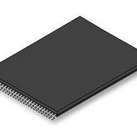
S29GL256P11TFI010 Spansion Inc., S29GL256P11TFI010 Datasheet - Page 48

S29GL256P11TFI010
Manufacturer Part Number
S29GL256P11TFI010
Description
Flash 3V 256Mb Mirrorbit highest address110ns
Manufacturer
Spansion Inc.
Specifications of S29GL256P11TFI010
Memory Type
NOR
Memory Size
256 Mbit
Access Time
110 ns
Data Bus Width
8 bit, 16 bit
Architecture
Uniform
Interface Type
Page-mode
Supply Voltage (max)
3.6 V
Supply Voltage (min)
2.7 V
Maximum Operating Current
50 mA
Mounting Style
SMD/SMT
Operating Temperature
+ 85 C
Package / Case
TSOP-56
Memory Configuration
128K X 16
Ic Interface Type
Parallel
Supply Voltage Range
2.7V To 3.6V
Memory Case Style
TSOP
No. Of Pins
56
Lead Free Status / RoHS Status
Lead free / RoHS Compliant
Lead Free Status / RoHS Status
Lead free / RoHS Compliant, Lead free / RoHS Compliant
Available stocks
Company
Part Number
Manufacturer
Quantity
Price
Company:
Part Number:
S29GL256P11TFI010
Manufacturer:
SPANSION
Quantity:
5 530
Company:
Part Number:
S29GL256P11TFI010
Manufacturer:
SPANSION
Quantity:
72
10.3
46
Secured Silicon Sector Entry/Exit Command Sequences
The system can access the Secured Silicon Sector region by issuing the three-cycle Enter Secured Silicon
Sector command sequence. The device continues to access the Secured Silicon Sector region until the
system issues the four-cycle Exit Secured Silicon Sector command sequence.
See Command Definition Table [Secured Silicon Sector Command Table, Appendix
Table 12.1 on page 61
sequences.
The Secured Silicon Sector Entry Command allows the following commands to be executed
After the system has written the Enter Secured Silicon Sector command sequence, it may read the Secured
Silicon Sector by using the addresses normally occupied by sector SA0 within the memory array. This mode
of operation continues until the system issues the Exit Secured Silicon Sector command sequence, or until
power is removed from the device.
Software Functions and Sample Code
The following are C functions and source code examples of using the Secured Silicon Sector Entry, Program,
and exit commands. Refer to the Spansion Low Level Driver User’s Guide (available soon on
www.spansion.com) for general information on Spansion Flash memory software development guidelines.
Note
Base = Base Address.
Note
Base = Base Address.
Once the Secured Silicon Sector is locked and verified, the system must write the Exit Secured Silicon
Sector Region command sequence which return the device to the memory array at sector 0.
Read customer and factory Secured Silicon areas
Program the customer Secured Silicon Sector
/* Example: SecSi Sector Entry Command */
/* Once in the SecSi Sector mode, you program */
/* words using the programming algorithm.
*( (UINT16 *)base_addr + 0x555 ) = 0x00AA;
*( (UINT16 *)base_addr + 0x2AA ) = 0x0055;
*( (UINT16 *)base_addr + 0x555 ) = 0x0088;
Unlock Cycle 1
Unlock Cycle 2
Unlock Cycle 1
Unlock Cycle 2
Program Setup
Entry Cycle
Program
Cycle
Cycle
through
D a t a
S29GL-P MirrorBit
Table 12.4 on page 65
Table 10.3 Secured Silicon Sector Program
S h e e t
Table 10.2 Secured Silicon Sector Entry
(LLD Function = lld_SecSiSectorEntryCmd)
Operation
Operation
(LLD Function = lld_ProgramCmd)
Write
Write
Write
Write
Write
Write
Write
( A d v a n c e
TM
Flash Family
*/
/* write unlock cycle 1
/* write unlock cycle 2
/* write Secsi Sector Entry Cmd
for address and data requirements for both command
Byte Address
Byte Address
Word Address
Base + AAAh
Base + AAAh
Base + AAAh
Base + AAAh
Base + 555h
Base + 555h
I n f o r m a t i o n )
Word Address
Word Address
Word Address
Base + 2AAh
Base + 2AAh
Base + 555h
Base + 555h
Base + 555h
Base + 555h
S29GL-P_00_A3 November 21, 2006
*/
*/
*/
Data Word
00AAh
00AAh
00A0h
0055h
0088h
0055h
Data
Data


