LIS302DLTR STMicroelectronics, LIS302DLTR Datasheet - Page 12
LIS302DLTR
Manufacturer Part Number
LIS302DLTR
Description
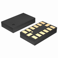
ACCELEROMETER 3AXIS MEMS 14-LGA
Manufacturer
STMicroelectronics
Datasheet
1.STEVAL-MKI006V1.pdf
(42 pages)
Specifications of LIS302DLTR
Featured Product
STM32 Cortex-M3 Companion Products
Axis
X, Y, Z
Acceleration Range
±2.3g, 9.2g
Sensitivity
18mg/digit, 72mg/digit
Voltage - Supply
2.16 V ~ 3.6 V
Output Type
Digital
Bandwidth
100Hz ~ 400Hz Selectable
Interface
I²C, SPI
Mounting Type
Surface Mount
Package / Case
14-LGA
Sensing Axis
X, Y, Z
Acceleration
2 g, 8 g
Digital Output - Number Of Bits
8 bit
Supply Voltage (max)
3.6 V
Supply Voltage (min)
2.16 V
Supply Current
0.3 mA
Maximum Operating Temperature
+ 85 C
Minimum Operating Temperature
- 40 C
Digital Output - Bus Interface
I2C, SPI
Shutdown
Yes
For Use With
497-9047 - BOARD DEMO ACCELEROMETER DIL24497-8373 - BOARD EVAL EXTENSION SN250497-8204 - BOARD ADAPTER LIS302SG DIL24497-8203 - BOARD DEMO LIS302SG497-6404 - BOARD EVAL SPZB260 MOD FOR STR9497-6342 - BOARD EVALUATION FOR LIS302DL497-6246 - BOARD EVAL ACCELEROM LIS302ALK497-6227 - BOARD ADAPTER 20DIP LIS3LV02DL497-6226 - BOARD EVAL ACCELEROM LIS3LV02DL
Lead Free Status / RoHS Status
Lead free / RoHS Compliant
Other names
497-5911-2
Available stocks
Company
Part Number
Manufacturer
Quantity
Price
Company:

Part Number:
LIS302DLTR
Manufacturer:
ST
Quantity:
1 056
Part Number:
LIS302DLTR
Manufacturer:
ST
Quantity:
20 000
Company:
Part Number:
LIS302DLTR8
Manufacturer:
SONY
Quantity:
26
Part Number:
LIS302DLTR8
Manufacturer:
ST
Quantity:
20 000


Mechanical and electrical specifications
2.3
2.3.1
1. Values are guaranteed at 10MHz clock frequency for SPI with both 4 and 3 wires, based on characterization results, not
2. Measurement points are done at 0.2·Vdd_IO and 0.8·Vdd_IO, for both Input and Output port
3. When no communication is on-going, data on CS, SPC, SDI and SDO are driven by internal pull-up resistors
12/42
SDO
CS
SPC
SDI
tested in production
Symbol
tdis(SO)
tc(SPC)
fc(SPC)
tsu(CS)
th(CS)
tsu(SI)
tv(SO)
th(SO)
th(SI)
(3)
(3)
(3)
(3)
Communication interface characteristics
SPI - Serial Peripheral Interface
Subject to general operating conditions for Vdd and Top.
Table 5.
Figure 3.
t
su(CS)
SPI clock cycle
SPI clock frequency
CS setup time
CS hold time
SDI input setup time
SDI input hold time
SDO valid output time
SDO output hold time
SDO output disable time
SPI slave timing values
SPI slave timing diagram
t
su(SI)
MSB IN
MSB OUT
t
h(SI)
Parameter
t
v(SO)
t
c(SPC)
(2)
t
h(SO)
Min.
100
15
5
8
5
6
Value
(1)
Max.
10
50
50
LSB IN
LSB OUT
t
h(CS)
LIS302DL
t
dis(SO)
MHz
Unit
ns
ns
(3)
(3)
(3)
(3)
Related parts for LIS302DLTR
Image
Part Number
Description
Manufacturer
Datasheet
Request
R

Part Number:
Description:
STMicroelectronics [RIPPLE-CARRY BINARY COUNTER/DIVIDERS]
Manufacturer:
STMicroelectronics
Datasheet:
Part Number:
Description:
STMicroelectronics [LIQUID-CRYSTAL DISPLAY DRIVERS]
Manufacturer:
STMicroelectronics
Datasheet:

Part Number:
Description:
BOARD EVAL FOR MEMS SENSORS
Manufacturer:
STMicroelectronics
Datasheet:
Part Number:
Description:
NPN TRANSISTOR POWER MODULE
Manufacturer:
STMicroelectronics
Datasheet:
Part Number:
Description:
TURBOSWITCH ULTRA-FAST HIGH VOLTAGE DIODE
Manufacturer:
STMicroelectronics
Datasheet:
Part Number:
Description:
Manufacturer:
STMicroelectronics
Datasheet:
Part Number:
Description:
DIODE / SCR MODULE
Manufacturer:
STMicroelectronics
Datasheet:
Part Number:
Description:
DIODE / SCR MODULE
Manufacturer:
STMicroelectronics
Datasheet:
Part Number:
Description:
Search -----> STE16N100
Manufacturer:
STMicroelectronics
Datasheet:
Part Number:
Description:
Search ---> STE53NA50
Manufacturer:
STMicroelectronics
Datasheet:
Part Number:
Description:
NPN Transistor Power Module
Manufacturer:
STMicroelectronics
Datasheet:
Part Number:
Description:
DIODE / SCR MODULE
Manufacturer:
STMicroelectronics
Datasheet: