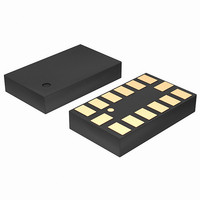
LIS302DLTR STMicroelectronics, LIS302DLTR Datasheet - Page 23

LIS302DLTR
Manufacturer Part Number
LIS302DLTR
Description
ACCELEROMETER 3AXIS MEMS 14-LGA
Manufacturer
STMicroelectronics
Datasheet
1.STEVAL-MKI006V1.pdf
(42 pages)
Specifications of LIS302DLTR
Featured Product
STM32 Cortex-M3 Companion Products
Axis
X, Y, Z
Acceleration Range
±2.3g, 9.2g
Sensitivity
18mg/digit, 72mg/digit
Voltage - Supply
2.16 V ~ 3.6 V
Output Type
Digital
Bandwidth
100Hz ~ 400Hz Selectable
Interface
I²C, SPI
Mounting Type
Surface Mount
Package / Case
14-LGA
Sensing Axis
X, Y, Z
Acceleration
2 g, 8 g
Digital Output - Number Of Bits
8 bit
Supply Voltage (max)
3.6 V
Supply Voltage (min)
2.16 V
Supply Current
0.3 mA
Maximum Operating Temperature
+ 85 C
Minimum Operating Temperature
- 40 C
Digital Output - Bus Interface
I2C, SPI
Shutdown
Yes
For Use With
497-9047 - BOARD DEMO ACCELEROMETER DIL24497-8373 - BOARD EVAL EXTENSION SN250497-8204 - BOARD ADAPTER LIS302SG DIL24497-8203 - BOARD DEMO LIS302SG497-6404 - BOARD EVAL SPZB260 MOD FOR STR9497-6342 - BOARD EVALUATION FOR LIS302DL497-6246 - BOARD EVAL ACCELEROM LIS302ALK497-6227 - BOARD ADAPTER 20DIP LIS3LV02DL497-6226 - BOARD EVAL ACCELEROM LIS3LV02DL
Lead Free Status / RoHS Status
Lead free / RoHS Compliant
Other names
497-5911-2
Available stocks
Company
Part Number
Manufacturer
Quantity
Price
Company:
Part Number:
LIS302DLTR
Manufacturer:
ST
Quantity:
1 056
Part Number:
LIS302DLTR
Manufacturer:
ST
Quantity:
20 000
Company:
Part Number:
LIS302DLTR8
Manufacturer:
SONY
Quantity:
26
Part Number:
LIS302DLTR8
Manufacturer:
ST
Quantity:
20 000
LIS302DL
5.2.3
The SPI Write command is performed with 16 clock pulses. Multiple byte write command is
performed adding blocks of 8 clock pulses at the previous one.
bit 0: WRITE bit. The value is 0.
bit 1: MS bit. When 0 do not increment address, when 1 increment address in multiple
writing.
bit 2 -7: address AD(5:0). This is the address field of the indexed register.
bit 8-15: data DI(7:0) (write mode). This is the data that will be written inside the device
(MSb first).
bit 16-... : data DI(...-8). Further data in multiple byte writing.
Figure 10. Multiple bytes SPI Write protocol (2 bytes example)
SPI Read in 3-wires mode
3-wires mode is entered by setting to 1 bit SIM (SPI Serial Interface Mode selection) in
CTRL_REG2.
Figure 11. SPI Read protocol in 3-wires mode
The SPI Read command is performed with 16 clock pulses:
bit 0: READ bit. The value is 1.
bit 1: MS bit. When 0 do not increment address, when 1 increment address in multiple
reading.
bit 2-7: address AD(5:0). This is the address field of the indexed register.
bit 8-15: data DO(7:0) (read mode). This is the data that will be read from the device (MSb
first).
Multiple read command is also available in 3-wires mode.
SPC
SDI
CS
SDI/O
SPC
CS
RW
MS
AD5 AD4 AD3 AD2 AD1 AD0
RW
MS
AD5 AD4 AD3 AD2 AD1 AD0
DI7 DI6 DI5 DI4 DI3 DI2 DI1 DI0 DI15 DI14 DI13 DI12 DI11 DI10 DI9 DI8
DO7 DO6 DO5 DO4 DO3 DO2 DO1 DO0
Digital interfaces
23/42


