LIS302DLTR STMicroelectronics, LIS302DLTR Datasheet - Page 15
LIS302DLTR
Manufacturer Part Number
LIS302DLTR
Description
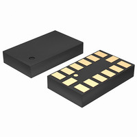
ACCELEROMETER 3AXIS MEMS 14-LGA
Manufacturer
STMicroelectronics
Datasheet
1.STEVAL-MKI006V1.pdf
(42 pages)
Specifications of LIS302DLTR
Featured Product
STM32 Cortex-M3 Companion Products
Axis
X, Y, Z
Acceleration Range
±2.3g, 9.2g
Sensitivity
18mg/digit, 72mg/digit
Voltage - Supply
2.16 V ~ 3.6 V
Output Type
Digital
Bandwidth
100Hz ~ 400Hz Selectable
Interface
I²C, SPI
Mounting Type
Surface Mount
Package / Case
14-LGA
Sensing Axis
X, Y, Z
Acceleration
2 g, 8 g
Digital Output - Number Of Bits
8 bit
Supply Voltage (max)
3.6 V
Supply Voltage (min)
2.16 V
Supply Current
0.3 mA
Maximum Operating Temperature
+ 85 C
Minimum Operating Temperature
- 40 C
Digital Output - Bus Interface
I2C, SPI
Shutdown
Yes
For Use With
497-9047 - BOARD DEMO ACCELEROMETER DIL24497-8373 - BOARD EVAL EXTENSION SN250497-8204 - BOARD ADAPTER LIS302SG DIL24497-8203 - BOARD DEMO LIS302SG497-6404 - BOARD EVAL SPZB260 MOD FOR STR9497-6342 - BOARD EVALUATION FOR LIS302DL497-6246 - BOARD EVAL ACCELEROM LIS302ALK497-6227 - BOARD ADAPTER 20DIP LIS3LV02DL497-6226 - BOARD EVAL ACCELEROM LIS3LV02DL
Lead Free Status / RoHS Status
Lead free / RoHS Compliant
Other names
497-5911-2
Available stocks
Company
Part Number
Manufacturer
Quantity
Price
Company:

Part Number:
LIS302DLTR
Manufacturer:
ST
Quantity:
1 056
Part Number:
LIS302DLTR
Manufacturer:
ST
Quantity:
20 000
Company:
Part Number:
LIS302DLTR8
Manufacturer:
SONY
Quantity:
26
Part Number:
LIS302DLTR8
Manufacturer:
ST
Quantity:
20 000


LIS302DL
2.5.2
2.5.3
2.5.4
Zero-g level
Zero-g level Offset (Off) describes the deviation of an actual output signal from the ideal
output signal if there is no acceleration present. A sensor in a steady state on a horizontal
surface will measure 0g in X axis and 0g in Y axis whereas the Z axis will measure 1g. The
output is ideally in the middle of the dynamic range of the sensor (content of OUT registers
00h, data expressed as 2’s complement number). A deviation from ideal value in this case is
called Zero-g offset. Offset is to some extent a result of stress to a precise MEMS sensor
and therefore the offset can slightly change after mounting the sensor onto a printed circuit
board or exposing it to extensive mechanical stress. Offset changes little over temperature,
see “Zero-g level change vs. temperature”. The Zero-g level of an individual sensor is stable
over lifetime. The Zero-g level tolerance describes the range of Zero-g levels of a population
of sensors.
Self test
Self Test allows to check the sensor functionality without moving it. The Self Test function is
off when the self-test bit of CTRL_REG1 (control register 1) is programmed to ‘0‘. When the
self-test bit of ctrl_reg1 is programmed to ‘1‘ an actuation force is applied to the sensor,
simulating a definite input acceleration. In this case the sensor outputs will exhibit a change
in their DC levels which is related to the selected full scale through the device sensitivity.
When Self Test is activated, the device output level is given by the algebraic sum of the
signals produced by the acceleration acting on the sensor and by the electrostatic test-force.
If the output signals change within the amplitude specified inside
working properly and the parameters of the interface chip are within the defined
specification.
Click and double click recognition
The Click and Double Click recognition functions help to create man-machine interface with
little software overload. The device can be configured to output an interrupt signal on
dedicated pin when tapped in any direction.
If the sensor is exposed to a single input stimulus it generates an interrupt request on inertial
interrupt pin (INT1 and/or INT2). A more advanced feature allows to generate and interrupt
request when a “double click” with programmable time between the two events enabling a
“mouse button like” use.
This function can be fully programmed by the user in terms of expected amplitude and
timing of the stimuli.
Mechanical and electrical specifications
Table
3, than the sensor is
15/42
Related parts for LIS302DLTR
Image
Part Number
Description
Manufacturer
Datasheet
Request
R

Part Number:
Description:
STMicroelectronics [RIPPLE-CARRY BINARY COUNTER/DIVIDERS]
Manufacturer:
STMicroelectronics
Datasheet:
Part Number:
Description:
STMicroelectronics [LIQUID-CRYSTAL DISPLAY DRIVERS]
Manufacturer:
STMicroelectronics
Datasheet:

Part Number:
Description:
BOARD EVAL FOR MEMS SENSORS
Manufacturer:
STMicroelectronics
Datasheet:
Part Number:
Description:
NPN TRANSISTOR POWER MODULE
Manufacturer:
STMicroelectronics
Datasheet:
Part Number:
Description:
TURBOSWITCH ULTRA-FAST HIGH VOLTAGE DIODE
Manufacturer:
STMicroelectronics
Datasheet:
Part Number:
Description:
Manufacturer:
STMicroelectronics
Datasheet:
Part Number:
Description:
DIODE / SCR MODULE
Manufacturer:
STMicroelectronics
Datasheet:
Part Number:
Description:
DIODE / SCR MODULE
Manufacturer:
STMicroelectronics
Datasheet:
Part Number:
Description:
Search -----> STE16N100
Manufacturer:
STMicroelectronics
Datasheet:
Part Number:
Description:
Search ---> STE53NA50
Manufacturer:
STMicroelectronics
Datasheet:
Part Number:
Description:
NPN Transistor Power Module
Manufacturer:
STMicroelectronics
Datasheet:
Part Number:
Description:
DIODE / SCR MODULE
Manufacturer:
STMicroelectronics
Datasheet: