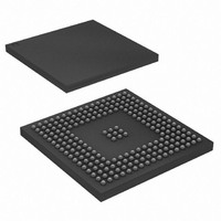
AT91SAM9260B-CU-999 Atmel, AT91SAM9260B-CU-999 Datasheet - Page 123

AT91SAM9260B-CU-999
Manufacturer Part Number
AT91SAM9260B-CU-999
Description
IC MCU ARM9 217LFBGA
Manufacturer
Atmel
Series
AT91SAMr
Datasheet
1.AT91SAM9260B-CU-999.pdf
(798 pages)
Specifications of AT91SAM9260B-CU-999
Core Processor
ARM9
Core Size
16/32-Bit
Speed
180MHz
Connectivity
EBI/EMI, Ethernet, I²C, MMC, SPI, SSC, UART/USART, USB
Peripherals
POR, WDT
Number Of I /o
96
Program Memory Size
32KB (32K x 8)
Program Memory Type
ROM
Ram Size
24K x 8
Voltage - Supply (vcc/vdd)
1.65 V ~ 1.95 V
Data Converters
A/D 4x10b
Oscillator Type
Internal
Operating Temperature
-40°C ~ 85°C
Package / Case
217-LFBGA
Processor Series
AT91SAMx
Core
ARM926EJ-S
Data Bus Width
32 bit
Data Ram Size
8 KB
Interface Type
2-Wire, EBI, I2S, SPI, USART
Maximum Clock Frequency
180 MHz
Number Of Programmable I/os
96
Number Of Timers
6
Maximum Operating Temperature
+ 85 C
Mounting Style
SMD/SMT
3rd Party Development Tools
JTRACE-ARM-2M, MDK-ARM, RL-ARM, ULINK2
Development Tools By Supplier
AT91SAM-ICE, AT91-ISP, AT91SAM9260-EK
Minimum Operating Temperature
- 40 C
On-chip Adc
10 bit, 4 Channel
For Use With
AT91SAM9260-EK - KIT EVAL FOR AT91SAM9260AT91SAM-ICE - EMULATOR FOR AT91 ARM7/ARM9
Lead Free Status / RoHS Status
Lead free / RoHS Compliant
Eeprom Size
-
Lead Free Status / Rohs Status
Details
Available stocks
Company
Part Number
Manufacturer
Quantity
Price
- Current page: 123 of 798
- Download datasheet (12Mb)
18. AT91SAM9260 Bus Matrix
18.1
18.2
18.2.1
6221I–ATARM–17-Jul-09
Description
Embedded Characteristics
Matrix Masters
The Bus Matrix implements a multi-layer AHB based on the AHB-Lite protocol that enables par-
allel access paths between multiple AHB masters and slaves in a system, thus increasing the
overall bandwidth. The Bus Matrix interconnects 6 AHB Masters to 5 AHB Slaves. The normal
latency to connect a master to a slave is one cycle except for the default master of the accessed
slave which is connected directly (zero cycle latency).
The Bus Matrix user interface is compliant with the ARM Advanced High-performance Bus and
provides a Chip Configuration User Interface with registers that allow the Bus Matrix to support
application specific features.
The Bus Matrix of the AT91SAM9260 manages six Masters, which means that each master can
perform an access concurrently with others, according the slave it accesses is available.
Each Master has its own decoder that can be defined specifically for each master. In order to
simplify the addressing, all the masters have the same decodings.
Table 18-1.
Master 0
Master 1
Master 2
• 6-layer Matrix, handling requests from 6 masters
• Programmable Arbitration strategy
• Burst Management
• One Address Decoder provided per Master
• Boot Mode Select
• Remap Command
– Fixed-priority Arbitration
– Round-Robin Arbitration, either with no default master, last accessed default master
– Breaking with Slot Cycle Limit Support
– Undefined Burst Length Support
– Three different slaves may be assigned to each decoded memory area: one for
– Non-volatile Boot Memory can be internal or external
– Selection is made by BMS pin sampled at reset
– Allows Remapping of an Internal SRAM in Place of the Boot Non-Volatile Memory
– Allows Handling of Dynamic Exception Vectors
or fixed default master
internal boot, one for external boot, one after remap
List of Bus Matrix Masters
ARM926
ARM926 Data
PDC
™
Instruction
AT91SAM9260
123
Related parts for AT91SAM9260B-CU-999
Image
Part Number
Description
Manufacturer
Datasheet
Request
R

Part Number:
Description:
Manufacturer:
ATMEL Corporation
Datasheet:

Part Number:
Description:
KIT EVAL FOR AT91SAM9260
Manufacturer:
Atmel
Datasheet:

Part Number:
Description:
AT91 ARM Thumb Microcontrollers
Manufacturer:
ATMEL [ATMEL Corporation]
Datasheet:

Part Number:
Description:
AT91 ARM Thumb Microcontrollers
Manufacturer:
ATMEL Corporation
Datasheet:

Part Number:
Description:
At91 Arm Thumb Microcontrollers
Manufacturer:
ATMEL Corporation
Datasheet:

Part Number:
Description:
MCU, MPU & DSP Development Tools DEV BRD FOR AT91SAM9260
Manufacturer:
Olimex Ltd.
Datasheet:

Part Number:
Description:
MCU, MPU & DSP Development Tools KICKSTART KIT FOR AT91SAM9 PLUS
Manufacturer:
IAR Systems

Part Number:
Description:
DEV KIT FOR AVR/AVR32
Manufacturer:
Atmel
Datasheet:

Part Number:
Description:
INTERVAL AND WIPE/WASH WIPER CONTROL IC WITH DELAY
Manufacturer:
ATMEL Corporation
Datasheet:

Part Number:
Description:
Low-Voltage Voice-Switched IC for Hands-Free Operation
Manufacturer:
ATMEL Corporation
Datasheet:

Part Number:
Description:
MONOLITHIC INTEGRATED FEATUREPHONE CIRCUIT
Manufacturer:
ATMEL Corporation
Datasheet:

Part Number:
Description:
AM-FM Receiver IC U4255BM-M
Manufacturer:
ATMEL Corporation
Datasheet:

Part Number:
Description:
Monolithic Integrated Feature Phone Circuit
Manufacturer:
ATMEL Corporation
Datasheet:

Part Number:
Description:
Multistandard Video-IF and Quasi Parallel Sound Processing
Manufacturer:
ATMEL Corporation
Datasheet:


