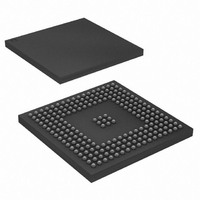
AT91SAM9260B-CU-999 Atmel, AT91SAM9260B-CU-999 Datasheet - Page 554

AT91SAM9260B-CU-999
Manufacturer Part Number
AT91SAM9260B-CU-999
Description
IC MCU ARM9 217LFBGA
Manufacturer
Atmel
Series
AT91SAMr
Datasheet
1.AT91SAM9260B-CU-999.pdf
(798 pages)
Specifications of AT91SAM9260B-CU-999
Core Processor
ARM9
Core Size
16/32-Bit
Speed
180MHz
Connectivity
EBI/EMI, Ethernet, I²C, MMC, SPI, SSC, UART/USART, USB
Peripherals
POR, WDT
Number Of I /o
96
Program Memory Size
32KB (32K x 8)
Program Memory Type
ROM
Ram Size
24K x 8
Voltage - Supply (vcc/vdd)
1.65 V ~ 1.95 V
Data Converters
A/D 4x10b
Oscillator Type
Internal
Operating Temperature
-40°C ~ 85°C
Package / Case
217-LFBGA
Processor Series
AT91SAMx
Core
ARM926EJ-S
Data Bus Width
32 bit
Data Ram Size
8 KB
Interface Type
2-Wire, EBI, I2S, SPI, USART
Maximum Clock Frequency
180 MHz
Number Of Programmable I/os
96
Number Of Timers
6
Maximum Operating Temperature
+ 85 C
Mounting Style
SMD/SMT
3rd Party Development Tools
JTRACE-ARM-2M, MDK-ARM, RL-ARM, ULINK2
Development Tools By Supplier
AT91SAM-ICE, AT91-ISP, AT91SAM9260-EK
Minimum Operating Temperature
- 40 C
On-chip Adc
10 bit, 4 Channel
For Use With
AT91SAM9260-EK - KIT EVAL FOR AT91SAM9260AT91SAM-ICE - EMULATOR FOR AT91 ARM7/ARM9
Lead Free Status / RoHS Status
Lead free / RoHS Compliant
Eeprom Size
-
Lead Free Status / Rohs Status
Details
Available stocks
Company
Part Number
Manufacturer
Quantity
Price
- Current page: 554 of 798
- Download datasheet (12Mb)
6221I–ATARM–17-Jul-09
The command ALL_SEND_CID and the fields and values for the MCI_CMDR Control Register
are described in
Table 34-4.
Note:
Table 34-5.
The MCI_ARGR contains the argument field of the command.
To send a command, the user must perform the following steps:
The command is sent immediately after writing the command register. The status bit CMDRDY
in the status register (MCI_SR) is asserted when the command is completed. If the command
requires a response, it can be read in the MCI response register (MCI_RSPR). The response
size can be from 48 bits up to 136 bits depending on the command. The MCI embeds an error
detection to prevent any corrupted data during the transfer.
The following flowchart shows how to send a command to the card and read the response if
needed. In this example, the status register bits are polled but setting the appropriate bits in the
interrupt enable register (MCI_IER) allows using an interrupt method.
CMD Index
CMD2
Field
CMDNB (command number)
RSPTYP (response type)
SPCMD (special command)
OPCMD (open drain command)
MAXLAT (max latency for command to
response)
TRCMD (transfer command)
TRDIR (transfer direction)
TRTYP (transfer type)
IOSPCMD (SDIO special command)
• Fill the argument register (MCI_ARGR) with the command argument.
• Set the command register (MCI_CMDR) (see
bcr means broadcast command with response.
ALL_SEND_CID Command Description
Fields and Values for MCI_CMDR Command Register
Type
bcr
Table 34-4
Argument
[31:0] stuff bits
and
Table
34-5.
Resp
R2
Value
2 (CMD2)
2 (R2: 136 bits response)
0 (not a special command)
1
0 (NID cycles ==> 5 cycles)
0 (No transfer)
X (available only in transfer command)
X (available only in transfer command)
0 (not a special command)
Abbreviation
ALL_SEND_CID
Table
34-5).
AT91SAM9260
Command
Description
Asks all cards to
send their CID
numbers on the
CMD line
554
Related parts for AT91SAM9260B-CU-999
Image
Part Number
Description
Manufacturer
Datasheet
Request
R

Part Number:
Description:
Manufacturer:
ATMEL Corporation
Datasheet:

Part Number:
Description:
KIT EVAL FOR AT91SAM9260
Manufacturer:
Atmel
Datasheet:

Part Number:
Description:
AT91 ARM Thumb Microcontrollers
Manufacturer:
ATMEL [ATMEL Corporation]
Datasheet:

Part Number:
Description:
AT91 ARM Thumb Microcontrollers
Manufacturer:
ATMEL Corporation
Datasheet:

Part Number:
Description:
At91 Arm Thumb Microcontrollers
Manufacturer:
ATMEL Corporation
Datasheet:

Part Number:
Description:
MCU, MPU & DSP Development Tools DEV BRD FOR AT91SAM9260
Manufacturer:
Olimex Ltd.
Datasheet:

Part Number:
Description:
MCU, MPU & DSP Development Tools KICKSTART KIT FOR AT91SAM9 PLUS
Manufacturer:
IAR Systems

Part Number:
Description:
DEV KIT FOR AVR/AVR32
Manufacturer:
Atmel
Datasheet:

Part Number:
Description:
INTERVAL AND WIPE/WASH WIPER CONTROL IC WITH DELAY
Manufacturer:
ATMEL Corporation
Datasheet:

Part Number:
Description:
Low-Voltage Voice-Switched IC for Hands-Free Operation
Manufacturer:
ATMEL Corporation
Datasheet:

Part Number:
Description:
MONOLITHIC INTEGRATED FEATUREPHONE CIRCUIT
Manufacturer:
ATMEL Corporation
Datasheet:

Part Number:
Description:
AM-FM Receiver IC U4255BM-M
Manufacturer:
ATMEL Corporation
Datasheet:

Part Number:
Description:
Monolithic Integrated Feature Phone Circuit
Manufacturer:
ATMEL Corporation
Datasheet:

Part Number:
Description:
Multistandard Video-IF and Quasi Parallel Sound Processing
Manufacturer:
ATMEL Corporation
Datasheet:


