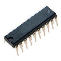
MCHC705JJ7CPE Freescale Semiconductor, MCHC705JJ7CPE Datasheet - Page 107

MCHC705JJ7CPE
Manufacturer Part Number
MCHC705JJ7CPE
Description
IC MCU 8BIT 224 BYTES RAM 20PDIP
Manufacturer
Freescale Semiconductor
Series
HC05r
Datasheet
1.MC705JJ7CDWE.pdf
(164 pages)
Specifications of MCHC705JJ7CPE
Core Processor
HC05
Core Size
8-Bit
Speed
2.1MHz
Connectivity
SIO
Peripherals
POR, Temp Sensor, WDT
Number Of I /o
14
Program Memory Size
6KB (6K x 8)
Program Memory Type
OTP
Ram Size
224 x 8
Voltage - Supply (vcc/vdd)
2.7 V ~ 5.5 V
Data Converters
A/D 4x12b
Oscillator Type
Internal
Operating Temperature
-40°C ~ 85°C
Package / Case
20-DIP (0.300", 7.62mm)
Processor Series
HC705JJ
Core
HC05
Data Bus Width
8 bit
Data Ram Size
224 B
Interface Type
SIOP
Maximum Clock Frequency
2.1 MHz
Number Of Programmable I/os
14
Number Of Timers
2
Maximum Operating Temperature
+ 85 C
Mounting Style
Through Hole
Minimum Operating Temperature
- 40 C
On-chip Adc
12 bit, 4 Channel
Package
20PDIP
Family Name
HC05
Maximum Speed
2.1 MHz
Operating Supply Voltage
3.3|5 V
Lead Free Status / RoHS Status
Lead free / RoHS Compliant
Eeprom Size
-
Lead Free Status / Rohs Status
Details
- Current page: 107 of 164
- Download datasheet (2Mb)
11.2 Timer Registers
The functional block diagram of the 16-bit free-running timer counter and timer registers is shown in
Figure
The timer registers (TMRH and TMRL) shown in
current high and low bytes of the 16-bit free-running counter. Writing to the timer registers has no effect.
Reset of the device presets the timer counter to $FFFC.
The TMRL latch is a transparent read of the LSB until a read of the TMRH takes place. A read of the
TMRH latches the LSB into the TMRL location until the TMRL is again read. The latched value remains
fixed even if multiple reads of the TMRH take place before the next read of the TMRL. Therefore, when
reading the MSB of the timer at TMRH, the LSB of the timer at TMRL must also be read to complete the
read sequence.
During power-on reset (POR), the counter is initialized to $FFFC and begins counting after the oscillator
startup delay. Because the counter is 16 bits and preceded by a fixed prescaler, the value in the counter
repeats every 262,144 internal bus clock cycles (524,288 oscillator cycles).
Freescale Semiconductor
11-2. The timer registers include a transparent buffer latch on the LSB of the 16-bit timer counter.
Address:
Address:
RESET
Reset:
Reset:
TMRH
READ
Read:
Read:
Write:
Write:
Figure 11-3. Programmable Timer Registers (TMRH and TMRL)
MC68HC705JJ7 • MC68HC705JP7 Advance Information Data Sheet, Rev. 4.1
$0018
$0018
Bit 15
Bit 7
Bit 7
Bit 7
1
1
Figure 11-2. Programmable Timer Block Diagram
$FFFC
READ
$0012
= Unimplemented
TIMER CONTROL REG.
14
6
1
6
6
1
TMRH ($0018)
OVERFLOW (TOF)
13
5
1
5
5
1
LATCH
16-BIT COUNTER
Figure 11-3
12
4
1
4
4
1
TMRL ($0019)
TMR LSB
TIMER STATUS REG.
11
3
1
3
3
1
are read-only locations which contain the
10
2
1
2
2
1
$0013
÷ 4
1
9
1
1
1
0
INTERNAL
INTERRUPT
(OSC ÷ 2)
READ
TMRL
REQUEST
INTERNAL
CLOCK
TIMER
DATA
BUS
Bit 0
Bit 8
Bit 0
Bit 0
1
0
Timer Registers
107
Related parts for MCHC705JJ7CPE
Image
Part Number
Description
Manufacturer
Datasheet
Request
R
Part Number:
Description:
Manufacturer:
Freescale Semiconductor, Inc
Datasheet:
Part Number:
Description:
Manufacturer:
Freescale Semiconductor, Inc
Datasheet:
Part Number:
Description:
Manufacturer:
Freescale Semiconductor, Inc
Datasheet:
Part Number:
Description:
Manufacturer:
Freescale Semiconductor, Inc
Datasheet:
Part Number:
Description:
Manufacturer:
Freescale Semiconductor, Inc
Datasheet:
Part Number:
Description:
Manufacturer:
Freescale Semiconductor, Inc
Datasheet:
Part Number:
Description:
Manufacturer:
Freescale Semiconductor, Inc
Datasheet:
Part Number:
Description:
Manufacturer:
Freescale Semiconductor, Inc
Datasheet:
Part Number:
Description:
Manufacturer:
Freescale Semiconductor, Inc
Datasheet:
Part Number:
Description:
Manufacturer:
Freescale Semiconductor, Inc
Datasheet:
Part Number:
Description:
Manufacturer:
Freescale Semiconductor, Inc
Datasheet:
Part Number:
Description:
Manufacturer:
Freescale Semiconductor, Inc
Datasheet:
Part Number:
Description:
Manufacturer:
Freescale Semiconductor, Inc
Datasheet:
Part Number:
Description:
Manufacturer:
Freescale Semiconductor, Inc
Datasheet:
Part Number:
Description:
Manufacturer:
Freescale Semiconductor, Inc
Datasheet:


