MCHC705JJ7CPE Freescale Semiconductor, MCHC705JJ7CPE Datasheet - Page 18

MCHC705JJ7CPE
Manufacturer Part Number
MCHC705JJ7CPE
Description
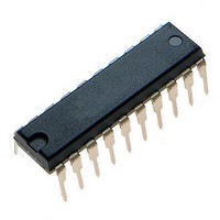
IC MCU 8BIT 224 BYTES RAM 20PDIP
Manufacturer
Freescale Semiconductor
Series
HC05r
Datasheet
1.MC705JJ7CDWE.pdf
(164 pages)
Specifications of MCHC705JJ7CPE
Core Processor
HC05
Core Size
8-Bit
Speed
2.1MHz
Connectivity
SIO
Peripherals
POR, Temp Sensor, WDT
Number Of I /o
14
Program Memory Size
6KB (6K x 8)
Program Memory Type
OTP
Ram Size
224 x 8
Voltage - Supply (vcc/vdd)
2.7 V ~ 5.5 V
Data Converters
A/D 4x12b
Oscillator Type
Internal
Operating Temperature
-40°C ~ 85°C
Package / Case
20-DIP (0.300", 7.62mm)
Processor Series
HC705JJ
Core
HC05
Data Bus Width
8 bit
Data Ram Size
224 B
Interface Type
SIOP
Maximum Clock Frequency
2.1 MHz
Number Of Programmable I/os
14
Number Of Timers
2
Maximum Operating Temperature
+ 85 C
Mounting Style
Through Hole
Minimum Operating Temperature
- 40 C
On-chip Adc
12 bit, 4 Channel
Package
20PDIP
Family Name
HC05
Maximum Speed
2.1 MHz
Operating Supply Voltage
3.3|5 V
Lead Free Status / RoHS Status
Lead free / RoHS Compliant
Eeprom Size
-
Lead Free Status / Rohs Status
Details
General Description
1.6.2 Ceramic Resonator Oscillator
In cost-sensitive applications, a ceramic resonator can be used in place of the crystal. The circuit in
Figure 1-3
should be followed, as the resonator parameters determine the external component values required for
maximum stability and reliable starting. The load capacitance values used in the oscillator circuit design
should include all stray capacitances. The ceramic resonator and components should be mounted as
close as possible to the pins for startup stabilization and to minimize output distortion. An internal startup
resistor of approximately 2 MΩ can be provided between OSC1 and OSC2 for the ceramic resonator type
oscillator by use of the OSCRES bit in the MOR.
1.6.3 RC Oscillator
The lowest cost oscillator is the RC oscillator configuration where a resistor is connected between the two
oscillator pins as shown in
The selection of the RC oscillator configuration is done by product part number selection as described in
Chapter 17 Ordering
1.6.4 External Clock
An external clock from another CMOS-compatible device can be connected to the OSC1 input, with the
OSC2 input not connected, as shown in
configuration is possible regardless of whether the crystal/ceramic resonator or RC oscillator
configuration is used.
1.6.5 Internal Low-Power Oscillator
An internal low-power oscillator (LPO) is provided which is the default oscillator out of reset. When
operating from this internal LPO, the other oscillator can be powered down by software to further conserve
power.
The selection of the LPO configuration is done by product part number selection as described in
Chapter 17 Ordering
1.7 RESET Pin
The RESET pin can be used as an input to reset the MCU to a known startup state by pulling it to the low
state. It also functions as an output to indicate that an internal COP watchdog, illegal address, or
low-voltage reset has occurred. The RESET pin contains a pullup device to allow the pin to be left
disconnected without an external pullup resistor. The RESET pin also contains a steering diode that,
when the power is removed, will discharge to V
between the RESET pin and V
noise immunity as an input.
18
(a) can be used for a ceramic resonator. The resonator manufacturer’s recommendations
Do not use the internal startup resistor between OSC1 and OSC2 for the
RC-type oscillator.
Do not use the internal startup resistor between OSC1 and OSC2 for the
external clock.
MC68HC705JJ7 • MC68HC705JP7 Advance Information Data Sheet, Rev. 4.1
Information.
Information.
Figure 1-3
SS
. The RESET pin also contains an internal Schmitt trigger to improve its
(b).
Figure 1-3
DD
NOTE
NOTE
any charge left on an external capacitor connected
(c). This oscillator can be selected via software. This
Freescale Semiconductor


