MC9S12DT256MPVE Freescale Semiconductor, MC9S12DT256MPVE Datasheet - Page 368
MC9S12DT256MPVE
Manufacturer Part Number
MC9S12DT256MPVE
Description
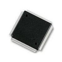
IC MCU 256K FLASH 25MHZ 112-LQFP
Manufacturer
Freescale Semiconductor
Series
HCS12r
Datasheet
1.S912XDG128F2MAL.pdf
(1348 pages)
Specifications of MC9S12DT256MPVE
Core Processor
HCS12
Core Size
16-Bit
Speed
25MHz
Connectivity
CAN, I²C, SCI, SPI
Peripherals
PWM, WDT
Number Of I /o
91
Program Memory Size
256KB (256K x 8)
Program Memory Type
FLASH
Eeprom Size
4K x 8
Ram Size
12K x 8
Voltage - Supply (vcc/vdd)
2.35 V ~ 5.25 V
Data Converters
A/D 8x10b
Oscillator Type
Internal
Operating Temperature
-40°C ~ 125°C
Package / Case
112-LQFP
Processor Series
S12D
Core
HCS12
Data Bus Width
16 bit
Data Ram Size
12 KB
Interface Type
CAN/I2C/SCI/SPI
Maximum Clock Frequency
25 MHz
Number Of Programmable I/os
91
Number Of Timers
1
Operating Supply Voltage
5 V to 2.5 V
Maximum Operating Temperature
+ 125 C
Mounting Style
SMD/SMT
3rd Party Development Tools
EWHCS12
Development Tools By Supplier
M68KIT912DP256
Minimum Operating Temperature
- 40 C
On-chip Adc
2 (8-ch x 10-bit)
No. Of I/o's
91
Eeprom Memory Size
4KB
Ram Memory Size
12KB
Cpu Speed
25MHz
No. Of Timers
1
No. Of Pwm Channels
8
Digital Ic Case Style
LQFP
Rohs Compliant
Yes
Lead Free Status / RoHS Status
Lead free / RoHS Compliant
Available stocks
Company
Part Number
Manufacturer
Quantity
Price

Company:
Part Number:
MC9S12DT256MPVE
Manufacturer:
Freescale Semiconductor
Quantity:
10 000


Chapter 8 Pulse-Width Modulator (S12PWM8B8CV1)
1
8.3.2.1
Each PWM channel has an enable bit (PWMEx) to start its waveform output. When any of the PWMEx
bits are set (PWMEx = 1), the associated PWM output is enabled immediately. However, the actual PWM
waveform is not available on the associated PWM output until its clock source begins its next cycle due to
the synchronization of PWMEx and the clock source.
An exception to this is when channels are concatenated. Once concatenated mode is enabled (CONxx bits
set in PWMCTL register), enabling/disabling the corresponding 16-bit PWM channel is controlled by the
368
PWMPER7
PWMDTY0
PWMDTY1
PWMDTY2
PWMDTY3
PWMDTY4
PWMDTY5
PWMDTY6
PWMDTY7
PWMSDN
Intended for factory test purposes only.
Register
Name
W
W
W
W
W
W
W
W
W
W
R
R
R
R
R
R
R
R
R
R
PWM Enable Register (PWME)
The first PWM cycle after enabling the channel can be irregular.
PWMIF
Bit 7
Bit 7
Bit 7
Bit 7
Bit 7
Bit 7
Bit 7
Bit 7
Bit 7
Bit 7
= Unimplemented or Reserved
Figure 8-2. PWM Register Summary (Sheet 3 of 3)
PWMIE
6
6
6
6
6
6
6
6
6
6
MC9S12XDP512 Data Sheet, Rev. 2.21
PWMRSTRT
5
0
5
5
5
5
5
5
5
5
5
NOTE
PWMLVL
4
4
4
4
4
4
4
4
4
4
3
0
3
3
3
3
3
3
3
3
3
PWM7IN
2
2
2
2
2
2
2
2
2
2
PWM7INL
Freescale Semiconductor
1
1
1
1
1
1
1
1
1
1
PWM7ENA
Bit 0
Bit 0
Bit 0
Bit 0
Bit 0
Bit 0
Bit 0
Bit 0
Bit 0
Bit 0
Related parts for MC9S12DT256MPVE
Image
Part Number
Description
Manufacturer
Datasheet
Request
R

Part Number:
Description:
Manufacturer:
Freescale Semiconductor, Inc
Datasheet:
Part Number:
Description:
Manufacturer:
Freescale Semiconductor, Inc
Datasheet:
Part Number:
Description:
Manufacturer:
Freescale Semiconductor, Inc
Datasheet:
Part Number:
Description:
Manufacturer:
Freescale Semiconductor, Inc
Datasheet:
Part Number:
Description:
Manufacturer:
Freescale Semiconductor, Inc
Datasheet:
Part Number:
Description:
Manufacturer:
Freescale Semiconductor, Inc
Datasheet:
Part Number:
Description:
Manufacturer:
Freescale Semiconductor, Inc
Datasheet:
Part Number:
Description:
Manufacturer:
Freescale Semiconductor, Inc
Datasheet:
Part Number:
Description:
Manufacturer:
Freescale Semiconductor, Inc
Datasheet:
Part Number:
Description:
Manufacturer:
Freescale Semiconductor, Inc
Datasheet:
Part Number:
Description:
Manufacturer:
Freescale Semiconductor, Inc
Datasheet:
Part Number:
Description:
Manufacturer:
Freescale Semiconductor, Inc
Datasheet:
Part Number:
Description:
Manufacturer:
Freescale Semiconductor, Inc
Datasheet:
Part Number:
Description:
Manufacturer:
Freescale Semiconductor, Inc
Datasheet:
Part Number:
Description:
Manufacturer:
Freescale Semiconductor, Inc
Datasheet: