MC9S12DT256MPVE Freescale Semiconductor, MC9S12DT256MPVE Datasheet - Page 703
MC9S12DT256MPVE
Manufacturer Part Number
MC9S12DT256MPVE
Description
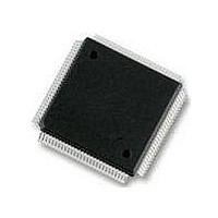
IC MCU 256K FLASH 25MHZ 112-LQFP
Manufacturer
Freescale Semiconductor
Series
HCS12r
Datasheet
1.S912XDG128F2MAL.pdf
(1348 pages)
Specifications of MC9S12DT256MPVE
Core Processor
HCS12
Core Size
16-Bit
Speed
25MHz
Connectivity
CAN, I²C, SCI, SPI
Peripherals
PWM, WDT
Number Of I /o
91
Program Memory Size
256KB (256K x 8)
Program Memory Type
FLASH
Eeprom Size
4K x 8
Ram Size
12K x 8
Voltage - Supply (vcc/vdd)
2.35 V ~ 5.25 V
Data Converters
A/D 8x10b
Oscillator Type
Internal
Operating Temperature
-40°C ~ 125°C
Package / Case
112-LQFP
Processor Series
S12D
Core
HCS12
Data Bus Width
16 bit
Data Ram Size
12 KB
Interface Type
CAN/I2C/SCI/SPI
Maximum Clock Frequency
25 MHz
Number Of Programmable I/os
91
Number Of Timers
1
Operating Supply Voltage
5 V to 2.5 V
Maximum Operating Temperature
+ 125 C
Mounting Style
SMD/SMT
3rd Party Development Tools
EWHCS12
Development Tools By Supplier
M68KIT912DP256
Minimum Operating Temperature
- 40 C
On-chip Adc
2 (8-ch x 10-bit)
No. Of I/o's
91
Eeprom Memory Size
4KB
Ram Memory Size
12KB
Cpu Speed
25MHz
No. Of Timers
1
No. Of Pwm Channels
8
Digital Ic Case Style
LQFP
Rohs Compliant
Yes
Lead Free Status / RoHS Status
Lead free / RoHS Compliant
Available stocks
Company
Part Number
Manufacturer
Quantity
Price

Company:
Part Number:
MC9S12DT256MPVE
Manufacturer:
Freescale Semiconductor
Quantity:
10 000


19.3.1.7
Each of the state sequencer states 1 to 3 features a dedicated control register to determine if transitions
from that state are allowed depending upon comparator matches or tag hits and to define the next state for
the state sequencer following a match. The 3 debug state control registers are located at the same address
in the register address map (0x0027). Each register can be accessed using the COMRV bits in DBGC1 to
blend in the required register (see
19.3.1.8
Read: Anytime
Write: Anytime when DBG not armed.
This register is visible at 0x0027 only with COMRV[1:0] = 00. The state control register 1 selects the
targeted next state while in State1. The matches refer to the match channels of the comparator match
control logic as depicted in
Register
associated DBGXCTL control register.
Freescale Semiconductor
0x0027
SC[3:0}
Reset
Field
3–0
W
R
(DBGXCTL)”. Comparators must be enabled by setting the comparator enable bit in the
State Control Bits — These bits select the targeted next state while in State1, based upon the match event.
See
The trigger priorities described in
the lower channel number ([0,1,2,3) has priority. The SC[3:0] encoding ensures that a match leading to final
state has priority over all other matches.
Debug State Control Registers
Debug State Control Register 1 (DBGSCR1)
0
0
7
Table
Unimplemented or Reserved
19-21.
Figure 19-10. Debug State Control Register 1 (DBGSCR1)
0
0
6
Table 19-19. State Control Register Access Encoding
Figure 19-1
COMRV
Table 19-20. DBGSCR1 Field Descriptions
00
01
10
11
Table
MC9S12XDP512 Data Sheet, Rev. 2.21
0
0
5
and described in
19-19).
Table 19-38
Visible State Control Register
0
0
4
dictate that in the case of simultaneous matches, the match on
Description
Section 19.3.1.11.1, “Debug Comparator Control
DBGSCR1
DBGSCR2
DBGSCR3
DBGSCR3
SC3
0
3
Chapter 19 S12X Debug (S12XDBGV2) Module
SC2
0
2
SC1
0
1
SC0
0
0
705
Related parts for MC9S12DT256MPVE
Image
Part Number
Description
Manufacturer
Datasheet
Request
R

Part Number:
Description:
Manufacturer:
Freescale Semiconductor, Inc
Datasheet:
Part Number:
Description:
Manufacturer:
Freescale Semiconductor, Inc
Datasheet:
Part Number:
Description:
Manufacturer:
Freescale Semiconductor, Inc
Datasheet:
Part Number:
Description:
Manufacturer:
Freescale Semiconductor, Inc
Datasheet:
Part Number:
Description:
Manufacturer:
Freescale Semiconductor, Inc
Datasheet:
Part Number:
Description:
Manufacturer:
Freescale Semiconductor, Inc
Datasheet:
Part Number:
Description:
Manufacturer:
Freescale Semiconductor, Inc
Datasheet:
Part Number:
Description:
Manufacturer:
Freescale Semiconductor, Inc
Datasheet:
Part Number:
Description:
Manufacturer:
Freescale Semiconductor, Inc
Datasheet:
Part Number:
Description:
Manufacturer:
Freescale Semiconductor, Inc
Datasheet:
Part Number:
Description:
Manufacturer:
Freescale Semiconductor, Inc
Datasheet:
Part Number:
Description:
Manufacturer:
Freescale Semiconductor, Inc
Datasheet:
Part Number:
Description:
Manufacturer:
Freescale Semiconductor, Inc
Datasheet:
Part Number:
Description:
Manufacturer:
Freescale Semiconductor, Inc
Datasheet:
Part Number:
Description:
Manufacturer:
Freescale Semiconductor, Inc
Datasheet: