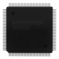
HD6417032F20V Renesas Electronics America, HD6417032F20V Datasheet - Page 19

HD6417032F20V
Manufacturer Part Number
HD6417032F20V
Description
SH1 ROMLESS LEAD FREE
Manufacturer
Renesas Electronics America
Series
SuperH® SH7030r
Datasheet
1.HD6417034AFI20.pdf
(689 pages)
Specifications of HD6417032F20V
Core Processor
SH-1
Core Size
32-Bit
Speed
20MHz
Connectivity
EBI/EMI, SCI
Peripherals
DMA, POR, PWM, WDT
Number Of I /o
32
Program Memory Type
ROMless
Ram Size
4K x 8
Voltage - Supply (vcc/vdd)
4.5 V ~ 5.5 V
Data Converters
A/D 8x10b
Oscillator Type
Internal
Operating Temperature
-20°C ~ 75°C
Package / Case
112-QFP
Lead Free Status / RoHS Status
Lead free / RoHS Compliant
Eeprom Size
-
Program Memory Size
-
Available stocks
Company
Part Number
Manufacturer
Quantity
Price
Company:
Part Number:
HD6417032F20V
Manufacturer:
TI
Quantity:
201
- Current page: 19 of 689
- Download datasheet (5Mb)
8.9
8.10 Bus Arbitration.................................................................................................................. 169
8.11 Usage Notes ...................................................................................................................... 172
Section 9 Direct Memory Access Controller (DMAC)
9.1
9.2
9.3
9.4
9.5
Section 10 16-Bit Integrated Timer Pulse Unit (ITU)
10.1 Overview........................................................................................................................... 223
Wait State Control............................................................................................................. 166
8.10.1 Operation of Bus Arbitration ............................................................................... 170
8.10.2 BACK Operation ................................................................................................. 171
8.11.1 Usage Notes on Manual Reset ............................................................................. 172
8.11.2 Usage Notes on Parity Data Pins DPH and DPL ................................................. 175
8.11.3 Maximum Number of States from BREQ Input to Bus Release.......................... 175
Overview........................................................................................................................... 179
9.1.1
9.1.2
9.1.3
9.1.4
Register Descriptions ........................................................................................................ 184
9.2.1
9.2.2
9.2.3
9.2.4
9.2.5
Operation........................................................................................................................... 192
9.3.1
9.3.2
9.3.3
9.3.4
9.3.5
9.3.6
Examples of Use ............................................................................................................... 217
9.4.1
9.4.2
9.4.3
Usage Notes ...................................................................................................................... 220
10.1.1 Features ................................................................................................................ 223
10.1.2 Block Diagram ..................................................................................................... 226
Features ................................................................................................................ 179
Block Diagram ..................................................................................................... 181
Pin Configuration................................................................................................. 182
Register Configuration......................................................................................... 183
DMA Source Address Registers 0–3 (SAR0–SAR3) .......................................... 184
DMA Destination Address Registers 0–3 (DAR0–DAR3).................................. 184
DMA Transfer Count Registers 0–3 (TCR0–TCR3) ........................................... 185
DMA Channel Control Registers 0–3 (CHCR0–CHCR3)................................... 185
DMA Operation Register (DMAOR)................................................................... 190
DMA Transfer Flow............................................................................................. 192
DMA Transfer Requests ...................................................................................... 194
Channel Priority ................................................................................................... 196
DMA Transfer Types ........................................................................................... 201
Number of Bus Cycle States and DREQ Pin Sample Timing.............................. 208
DMA Transfer Ending Conditions....................................................................... 216
DMA Transfer between On-Chip RAM and Memory-Mapped External
Example of DMA Transfer between On-Chip SCI and External Memory .......... 218
Example of DMA Transfer Between On-Chip A/D Converter and External
Device .................................................................................................................. 217
Memory................................................................................................................ 219
Rev. 7.00 Jan 31, 2006 page xvii of xxvi
.............................................. 223
............................................ 179
Related parts for HD6417032F20V
Image
Part Number
Description
Manufacturer
Datasheet
Request
R

Part Number:
Description:
KIT STARTER FOR M16C/29
Manufacturer:
Renesas Electronics America
Datasheet:

Part Number:
Description:
KIT STARTER FOR R8C/2D
Manufacturer:
Renesas Electronics America
Datasheet:

Part Number:
Description:
R0K33062P STARTER KIT
Manufacturer:
Renesas Electronics America
Datasheet:

Part Number:
Description:
KIT STARTER FOR R8C/23 E8A
Manufacturer:
Renesas Electronics America
Datasheet:

Part Number:
Description:
KIT STARTER FOR R8C/25
Manufacturer:
Renesas Electronics America
Datasheet:

Part Number:
Description:
KIT STARTER H8S2456 SHARPE DSPLY
Manufacturer:
Renesas Electronics America
Datasheet:

Part Number:
Description:
KIT STARTER FOR R8C38C
Manufacturer:
Renesas Electronics America
Datasheet:

Part Number:
Description:
KIT STARTER FOR R8C35C
Manufacturer:
Renesas Electronics America
Datasheet:

Part Number:
Description:
KIT STARTER FOR R8CL3AC+LCD APPS
Manufacturer:
Renesas Electronics America
Datasheet:

Part Number:
Description:
KIT STARTER FOR RX610
Manufacturer:
Renesas Electronics America
Datasheet:

Part Number:
Description:
KIT STARTER FOR R32C/118
Manufacturer:
Renesas Electronics America
Datasheet:

Part Number:
Description:
KIT DEV RSK-R8C/26-29
Manufacturer:
Renesas Electronics America
Datasheet:

Part Number:
Description:
KIT STARTER FOR SH7124
Manufacturer:
Renesas Electronics America
Datasheet:

Part Number:
Description:
KIT STARTER FOR H8SX/1622
Manufacturer:
Renesas Electronics America
Datasheet:

Part Number:
Description:
KIT DEV FOR SH7203
Manufacturer:
Renesas Electronics America
Datasheet:


