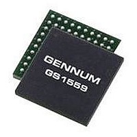
GS1559CBE2 GENNUM, GS1559CBE2 Datasheet - Page 12

GS1559CBE2
Manufacturer Part Number
GS1559CBE2
Description
IC, DES, 48.5MHZ 20BIT 1.485GBPS BGA-100
Manufacturer
GENNUM
Datasheet
1.GS1559CBE2.pdf
(73 pages)
Specifications of GS1559CBE2
Supply Voltage Range
1.71V To 1.89V, 3.13V To 3.47V
Operating Temperature Range
0°C To +70°C
Digital Ic Case Style
BGA
No. Of Pins
100
Termination Type
SMD
Control Interface
Serial
Lead Free Status / RoHS Status
Lead free / RoHS Compliant
Table 1-1: Pin Descriptions (Continued)
Number
Pin
G4
G5
G6
SMPTE_BYPASS
IOPROC_EN/DIS
RESET_TRST
Name
Synchronous
Synchronous
Synchronous
30572 - 7
Timing
Non
Non
Non
May 2007
Output
Type
Input /
Input
Input
Description
CONTROL SIGNAL INPUT
Signal levels are LVCMOS/LVTTL compatible.
Used to enable or disable I/O processing features.
When set HIGH, the following I/O processing features of the device are
enabled:
To enable a subset of these features, keep IOPROC_EN/DIS HIGH and
disable the individual feature(s) in the IOPROC_DISABLE register
accessible via the host interface.
When set LOW, the I/O processing features of the device are disabled,
regardless of whether the features are enabled in the IOPROC_DISABLE
register.
CONTROL SIGNAL INPUT / STATUS SIGNAL OUTPUT
Signal levels are LVCMOS/LVTTL compatible.
This pin will be an input set by the application layer in slave mode, and will
be an output set by the device in master mode.
Master Mode (MASTER/SLAVE = HIGH)
The SMPTE_BYPASS signal will be HIGH only when the device has
locked to a SMPTE compliant data stream. It will be LOW otherwise.
Slave Mode (MASTER/SLAVE = LOW)
When set HIGH in conjunction with DVB_ASI = LOW, the device will be
configured to operate in SMPTE mode. All I/O processing features may be
enabled in this mode.
When set LOW, the device will not support the descrambling, decoding or
word alignment of received SMPTE data. No I/O processing features will
be available.
CONTROL SIGNAL INPUT
Signal levels are LVCMOS/LVTTL compatible.
Used to reset the internal operating conditions to default settings and to
reset the JTAG test sequence.
Host Mode (JTAG/HOST = LOW)
When asserted LOW, all functional blocks will be set to default conditions
and all input and output signals become high impedance, including the
serial digital outputs SDO and SDO.
Must be set HIGH for normal device operation.
NOTE: When in slave mode, reset the device after the SD/HD input has
been initially configured, and after each subsequent SD/HD data rate
change.
JTAG Test Mode (JTAG/HOST = HIGH)
When asserted LOW, all functional blocks will be set to default and the
JTAG test sequence will be held in reset.
When set HIGH, normal operation of the JTAG test sequence resumes.
• EDH CRC Error Correction (SD-only)
• ANC Data Checksum Correction
• Line-based CRC Error Correction (HD-only)
• Line Number Error Correction (HD-only)
• TRS Error Correction
• Illegal Code Remapping
GS1559 Data Sheet
12 of 73


