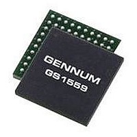
GS1559CBE2 GENNUM, GS1559CBE2 Datasheet - Page 63

GS1559CBE2
Manufacturer Part Number
GS1559CBE2
Description
IC, DES, 48.5MHZ 20BIT 1.485GBPS BGA-100
Manufacturer
GENNUM
Datasheet
1.GS1559CBE2.pdf
(73 pages)
Specifications of GS1559CBE2
Supply Voltage Range
1.71V To 1.89V, 3.13V To 3.47V
Operating Temperature Range
0°C To +70°C
Digital Ic Case Style
BGA
No. Of Pins
100
Termination Type
SMD
Control Interface
Serial
Lead Free Status / RoHS Status
Lead free / RoHS Compliant
4.12 GSPI Host Interface
4.12.1 Command Word Description
MSB
R/W
RSV
RSV
The GSPI, or Gennum Serial Peripheral Interface, is a 4-wire interface provided to
allow the host to enable additional features of the device and /or to provide
additional status information through configuration registers in the GS1559.
The GSPI comprises a serial data input signal SDIN, serial data output signal
SDOUT, an active low chip select CS, and a burst clock SCLK. The burst clock
must have a duty cycle between 40% and 60%.
Because these pins are shared with the JTAG interface port, an additional control
signal pin JTAG/HOST is provided. When JTAG/HOST is LOW, the GSPI interface
is enabled.
When operating in GSPI mode, the SCLK, SDIN, and CS signals are provided by
the host interface. The SDOUT pin is a high-impedance output allowing multiple
devices to be connected in parallel and selected via the CS input. The interface is
illustrated in
All read or write access to the GS1559 is initiated and terminated by the host
processor. Each access always begins with a 16-bit command word on SDIN
indicating the address of the register of interest. This is followed by a 16-bit data
word on SDIN in write mode, or a 16-bit data word on SDOUT in read mode.
Figure 4-9: Gennum Serial Peripheral Interface (GSPI)
The command word is transmitted MSB first and contains a read/write bit, nine
reserved bits and a 6-bit register address. Set R/W = '1' to read and R/W = '0' to
write from the GSPI.
Command words are clocked into the GS1559 on the rising edge of the serial clock
SCLK. The appropriate chip select, CS, signal must be asserted low a minimum of
1.5ns (t
proper operation.
Each command word must be followed by only one data word to ensure proper
operation.
30572 - 7
RSV
Application Host
0
RSV
in
SDOUT
SCLK
SDIN
Figure 4-12
May 2007
Figure
CS
RSV
4-9.
RSV
and
RSV
Figure
SCLK
SDIN
CS
SDOUT
RSV
4-13) before the first clock edge to ensure
GS1559
RSV
A5
A4
GS1559 Data Sheet
A3
A2
A1
63 of 73
A0
LSB


