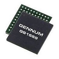
GS1559CBE2 GENNUM, GS1559CBE2 Datasheet - Page 55

GS1559CBE2
Manufacturer Part Number
GS1559CBE2
Description
IC, DES, 48.5MHZ 20BIT 1.485GBPS BGA-100
Manufacturer
GENNUM
Datasheet
1.GS1559CBE2.pdf
(73 pages)
Specifications of GS1559CBE2
Supply Voltage Range
1.71V To 1.89V, 3.13V To 3.47V
Operating Temperature Range
0°C To +70°C
Digital Ic Case Style
BGA
No. Of Pins
100
Termination Type
SMD
Control Interface
Serial
Lead Free Status / RoHS Status
Lead free / RoHS Compliant
Table 4-13: Host Interface Description for EDH Calculation Range Registers (Continued)
4.10.5.3 Lock Error Detection
4.10.5.4 Ancillary Data Checksum Error Detection
Register Name
FF_LINE_START_F0
Address: 016h
FF_LINE_END_F0
Address: 017h
FF_LINE_START_F1
Address: 018h
FF_LINE_END_F1
Address: 019h
Bit
15-10
9-0
15-10
9-0
15-10
9-0
15-10
9-0
Name
–
FF_LINE_START_F0[9:0]
–
FF_LINE_END_F0[9:0]
–
FF_LINE_START_F1[9:0]
–
FF_LINE_END_F1[9:0]
The LOCKED pin of the GS1559 indicates the lock status of the reclocker and lock
detect blocks of the device. Only when the LOCKED pin is asserted HIGH has the
device correctly locked to the received data stream, (see
The GS1559 will also indicate lock error to the host interface when LOCKED =
LOW by setting the LOCK_ERR bit in the ERROR_STATUS register HIGH.
The GS1559 will calculate checksums for all received ancillary data and compare
the calculated values to the received checksum words. If a mismatch is detected,
the error is flagged in the CCS_ERR and/or YCS_ERR bits of the
ERROR_STATUS register.
When operating in HD mode, (SD/HD = LOW), the device will make comparisons
on both the Y and C channels separately. If an error condition in the Y channel is
detected, the YCS_ERR bit will be set HIGH. If an error condition in the C channel
is detected, the CCS_ERR bit will be set HIGH.
When operating in SD mode, (SD/HD = HIGH), only the YCS_ERR bit will be set
HIGH when checksum errors are detected.
Although the GS1559 will calculate and compare checksum values for all ancillary
data types by default, the host interface may program the device to check only
certain types of ancillary data checksums.
This is accomplished via the ANC_TYPE register as described in
Ancillary Data Detection on page
30572 - 7
May 2007
Description
Not Used.
Field 0 Full Field start line data used to set EDH
calculation range outside of SMPTE RP 165
values.
Not Used.
Field 0 Full Field start line data used to set EDH
calculation range outside of SMPTE RP 165
values.
Not Used.
Field 1 Full Field start line data used to set EDH
calculation range outside of SMPTE RP 165
values.
Not Used.
Field 1 Full Field end line data used to set EDH
calculation range outside of SMPTE RP 165
values.
45.
GS1559 Data Sheet
Lock Detect on page
R/W
R/W
R/W
R/W
R/W
Programmable
–
–
–
–
Default
55 of 73
–
0
–
0
–
0
–
0
31).


