BS1D200P10 SANYO DENKI - SANMOTION, BS1D200P10 Datasheet - Page 10
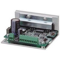
BS1D200P10
Manufacturer Part Number
BS1D200P10
Description
Stepper Motor Driver
Manufacturer
SANYO DENKI - SANMOTION
Datasheet
1.BS1D200P10.pdf
(64 pages)
Specifications of BS1D200P10
No. Of Phases
Two
Output Voltage Max
40V
Output Current
10mA
Supply Voltage Min
24VDC
Operating Temperature Max
50°C
Length/height, External
29mm
External Width
64mm
Current Limit Max
3A
Supply Voltage Range
24VDC To 36VDC
Rohs Compliant
Yes
Approval Bodies
CE / CUL / EN / TUV / UL
External Depth
56mm
Lead Free Status / RoHS Status
Lead free / RoHS Compliant


9
2-phase STEPPING SYSTEMS
■
(
■
WIRING
Signal
General-purpose
input common
Alarm clear signal
General-purpose
input 1
Emergency stop
input
Origin signal
+ direction
overtravel signal
General-purpose
input 2
Emergency stop
input
Origin signal
Alarm clear signal
- direction
overtravel signal
General-purpose
input 3
Emergency stop
input
Origin signal
Alarm clear signal
Signal
CW pulse input
(
Pulse train input
CCW pulse input
(
Rotational
General-purpose
input common
Power down
input
Step angle
select input
direction input
standard
standard
Standard
Standard
Specification
Specification Summary of Input/Output Signals (Serial I/F mode)
Specification Summary of Input/Output Signals (Pulse train I/F mode)
)
) )
)
)
Reference
Designation
Reference
Designation
CCW
+COM
CW
CCW+
U/D
+COM
ALMC
ALMC
ALMC
−
CK
EMG
EMG
EMG
CW+
U/D+
ORG
ORG
ORG
+OT
CK+
EXT
IN1
IN2
IN3
PD
OT
−
−
−
−
Pin
Number
Pin
Number
6
6
6
6
6
7
7
7
7
7
8
8
8
8
8
1
2
1
2
3
4
3
4
6
6
7
Function Summary
Input signal common of the 6 to 9 pins
DC 5V is input.
Recoverable alarms are cleared.
Internal photo coupler off
This is a general-purpose input signal that can be
used by program driving.
Internal photo coupler on
Internal photo coupler off
The emergency stop signal is input.
Internal photo coupler on
Internal photo coupler of
The origin signal used for the return to origin
operation is input.
Internal photo coupler on
Internal photo coupler off
An overtravel signal in the + direction is input.
Internal photo coupler on
arrived
Internal photo coupler off
arrived
This is a general-purpose input signal that can be
used by program driving.
Internal photo coupler on
Internal photo coupler off
The emergency stop signal is input.
Internal photo coupler on
Internal photo coupler off
The origin signal used for the return to origin
operation is input.
Internal photo coupler on
Internal photo coupler off
Recoverable alarms are cleared.
Internal photo coupler off
An overtravel signal in the - direction is input.
Internal photo coupler on
arrived
Internal photo coupler off
arrived
This is a general-purpose input signal that can be
used by program driving.
Internal photo coupler on
Internal photo coupler off
emergency stop signal is input.
Internal photo coupler on
Internal photo coupler off
The origin signal used for the return to origin
operation is input.
Internal photo coupler on
Internal photo coupler off
Recoverable alarms are cleared.
Internal photo coupler off
Function Summary
When 2 input mode ,
Input drive pulse rotating CW direction.
When 1 input mode ,
Input drive pulse train for motor rotation.
When 2 input mode ,
Input drive pulse rotating CCW direction.
When 1 input mode ,
Input motor rotational direction signal.
Internal photo coupler ON
Internal photo coupler OFF
Input signal common of the 6 to 9 pins
DC5V is input.
Inputting PD signal will cut off
flowing to the Motor
the Power low function is possible
PD input signal on
…
PD input signal off
…
FULL/HALF select input will become valid by inputting
EXT signal.
EXT input signal on
…
EXT input signal off
…
PD function is valid.
PD function is invalid.
External input signal F/H is valid
Main body rotary switch S.S is valid
(
(
(
(
internal photo coupler on
(
internal photo coupler off
internal photo coupler on
internal photo coupler off
With dip switch select, change to
…
…
…
…
…
…
…
…
…
…
…
…
…
…
…
…
→
…
…
…
…
→
…
…
→
…
Emergency stop
…
No emergency stop
Origin signal on
No emergency stop
Origin signal on
No emergency stop
Origin signal on
General purpose input 1 on
Origin signal off
General purpose input 2 on
Emergency stop
- direction overtravel
General purpose input 3 on
Emergency stop
+ direction overtravel not
+ direction overtravel
General purpose input 2 off
- direction overtravel not
on
General purpose input 1 off
Origin signal off
on
General purpose input 3 off
Origin signal off
on
CW direction
CCW direction
(
…
…
…
Alarm clear
Alarm clear
Alarm clear
power off
)
.
)
the current
)
)
)
)
※
viewing the Motor from output shaft side.
Signal
Emergency stop
signal
General-purpose
input 4c
Origin signal
Alarm clear signal
During motor
operation
During program
execution
Zone signal
During program
execution
During motor
operation
Zone signal
Alarm output
Output signal
common
DATA+
DATA
Signal
FULL/HALF
select input
Emergency
stop
During motor
operation
Phase origin
monitor output
Alarm output
Output signal
common
As for the Motor rotational direction, CW direction is regard as the clockwise revolution by
−
Reference
Designation
Reference
Designation
OUT_COM
OUT_COM
DATA
DATA+
ALMC
BUSY
PEND
ZONE
PEND
BUSY
ZONE
BUSY
EMG
EMG
MON
ORG
ALM
ALM
IN4
F/H
−
Pin
Number
Pin
Number
10
10
10
11
11
11
12
13
14
15
10
11
12
13
9
9
9
9
8
9
Function Summary
The emergency stop signal is input.
Internal photo coupler on
Internal photo coupler off
This is a general-purpose input signal that can be
used by program driving.
Internal photo coupler on
Internal photo coupler off
The origin signal used for the return to origin
operation is input.
Internal photo coupler on
Internal photo coupler off
alarms are cleared.
Internal photo coupler off
The operation status of the motor is output.
Internal photo coupler on
Internal photo coupler off
The execution status of the program is output.
Internal photo coupler on
Internal photo coupler off
complete
on when the current position is inside the
coordinates that were set beforehand.
The execution status of the program is output.
Internal photo coupler on
Internal photo coupler off
complete
The operation status of the motor is output.
Internal photo coupler on
Internal photo coupler off
Turns on when the current position is inside the
coordinates that were set beforehand.
When various alarm circuits operate in the driver, an
external signal is output.
At this time, the stepping motor becomes non excited
status.
It is for the output signal common.
It is for the serial signal.
It is for the serial signal.
Function Summary
When EXT input signal on
(
F/H input signal on
…
F/H input signal off
…
The emergency stop signal is input.
Internal photo coupler on
Internal photo coupler off
The operation status of the motor is output.
Internal photo coupler on
…
Internal photo coupler off
…
When the excitation phase is at the origin
turns on.
When FULL step, ON once for 4 pulses, when HALF step,
ON once for 8 pulses.
When alarm circuits actuated inside the Driver, outputs
signals to outside. Then the Stepping motor becomes
unexcited status.
It is for the output signal common.
internal photo coupler on
During motor operation
During motor stop
HALF step
FULL step
(
(
internal photo coupler on
internal photo coupler off
…
…
…
…
…
…
…
…
…
…
…
…
…
…
→
…
)
…
No emergency stop
Emergency stop
General purpose input 4 on
Origin signal on
During motor operation
During motor stop
During program execution
Program execution
During program execution
Program execution
During motor operation
During motor stop
General purpose input 4 off
Origin signal off
on
No emergency stop
,
Emergency stop
…
Alarm clear
(
in power on
)
)
)
it
Related parts for BS1D200P10
Image
Part Number
Description
Manufacturer
Datasheet
Request
R

Part Number:
Description:
MINISTEP BIPOLAR CHOPPER DRIVE, 2, 110 TO 230VAC
Manufacturer:
SANYO DENKI - SANMOTION
Datasheet:

Part Number:
Description:
MINISTEP BIPOLAR CHOPPER DRIVE, 2, 25 TO 45VDC
Manufacturer:
SANYO DENKI - SANMOTION
Datasheet:
Part Number:
Description:
MINISTEP BIPOLAR CHOPPER DRIVE, 2, 25 TO 45VDC
Manufacturer:
SANYO DENKI - SANMOTION
Datasheet:
Part Number:
Description:
MINISTEP BIPOLAR CHOPPER DRIVE, 2, 100 TO 120VAC
Manufacturer:
SANYO DENKI - SANMOTION
Datasheet:

Part Number:
Description:
CONTROLLER, STEPPER, 4 OPTIONAL
Manufacturer:
SANYO DENKI - SANMOTION
Datasheet: