BS1D200P10 SANYO DENKI - SANMOTION, BS1D200P10 Datasheet - Page 24
BS1D200P10
Manufacturer Part Number
BS1D200P10
Description
Stepper Motor Driver
Manufacturer
SANYO DENKI - SANMOTION
Datasheet
1.BS1D200P10.pdf
(64 pages)
Specifications of BS1D200P10
No. Of Phases
Two
Output Voltage Max
40V
Output Current
10mA
Supply Voltage Min
24VDC
Operating Temperature Max
50°C
Length/height, External
29mm
External Width
64mm
Current Limit Max
3A
Supply Voltage Range
24VDC To 36VDC
Rohs Compliant
Yes
Approval Bodies
CE / CUL / EN / TUV / UL
External Depth
56mm
Lead Free Status / RoHS Status
Lead free / RoHS Compliant


23 23
Operation, Connection, and Function
■
Unipolar
Bipolar
■
The CW rotation direction of stepping motor means the clockwise direction rotation as
viewed from the output shaft side
counterclockwise direction rotation as viewed from the output shaft side
7
7
2-phase STEPPING SYSTEMS
Signal name
C W p u l s e i n p u t
(
Pulse column input
C C W p u l s e i n p u t
(
Rotation direction
input
Power down input
P h a s e o r i g i n
monitor output
Alarm output
standard
standard
Specification summary of CN1 I/O signal
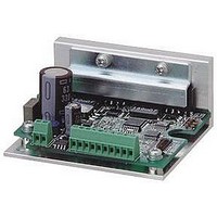
Each section name of the drivers
3
DC input
3
)
)
1
1
5
5
CN1 Pin
number
10
1
2
1
2
3
4
3
4
5
6
7
8
9
Specifications
(
flange side
Function
When using 2-input mode
Drive pulse for the CW direction rotation is input.
When using Pulse and direction mode
Drive pulse train for the stepping motor rotation is
input.
When using 2-input mode
Drive pulse for the CCW direction rotation is input.
The rotation direction signal of stepping motor is
input for the Pulse and direction mode .
Internal photocoupler ON
Internal photocoupler OFF
Inputting the PD signal cuts OFF the current flowing
through the stepping motor.
Iinternal photocoupler ON
Iinternal photocoupler OFF
It is turned ON when the excitation phase is at the
origin
It is turned ON once per 10 pulses when setting to
HALF step.
It is turned ON once per 20 pulses when setting to
FULL step.
The signal is externally output when one of several
alarm circuits operates in the PM driver. At this time,
the stepping motor is in the unexcited state.
2
2
(
)
in the state when the power is turned ON
. The CCW rotation direction means the
6
6
4
4
…
…
…
…
CW direction
PD function enabled
PD function disabled
CCW direction
(
flange side
1
2
3
4
5
6
7
1
2
3
4
5
6
7
Power supply connector
Connect the main circuit power supply.
I/O signal connector
Connect the I/O signal.
LED for power supply monitor
Lit up when the main circuit power supply is connected.
Function selection DIP switchpack
Select the function depending on your specification.
Driving current selection switch
You can select the value of the motor current when driving.
LED for alarm display
Lit when an alarm is generated.
Motor connector
Connect the motor s power line.
)
.
)
(
(
CN2
CN2
(
(
(
(
CN1
CN1
)
)
ALM
ALM
(
(
)
)
CN3
CN3
)
)
(
(
)
)
POW
POW
(
(
RUN
RUN
)
)
)
)
Related parts for BS1D200P10
Image
Part Number
Description
Manufacturer
Datasheet
Request
R

Part Number:
Description:
MINISTEP BIPOLAR CHOPPER DRIVE, 2, 110 TO 230VAC
Manufacturer:
SANYO DENKI - SANMOTION
Datasheet:

Part Number:
Description:
MINISTEP BIPOLAR CHOPPER DRIVE, 2, 25 TO 45VDC
Manufacturer:
SANYO DENKI - SANMOTION
Datasheet:
Part Number:
Description:
MINISTEP BIPOLAR CHOPPER DRIVE, 2, 25 TO 45VDC
Manufacturer:
SANYO DENKI - SANMOTION
Datasheet:
Part Number:
Description:
MINISTEP BIPOLAR CHOPPER DRIVE, 2, 100 TO 120VAC
Manufacturer:
SANYO DENKI - SANMOTION
Datasheet:

Part Number:
Description:
CONTROLLER, STEPPER, 4 OPTIONAL
Manufacturer:
SANYO DENKI - SANMOTION
Datasheet: