BS1D200P10 SANYO DENKI - SANMOTION, BS1D200P10 Datasheet - Page 9
BS1D200P10
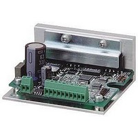
Manufacturer Part Number
BS1D200P10
Description
Stepper Motor Driver
Manufacturer
SANYO DENKI - SANMOTION
Datasheet
1.BS1D200P10.pdf
(64 pages)
Specifications of BS1D200P10
No. Of Phases
Two
Output Voltage Max
40V
Output Current
10mA
Supply Voltage Min
24VDC
Operating Temperature Max
50°C
Length/height, External
29mm
External Width
64mm
Current Limit Max
3A
Supply Voltage Range
24VDC To 36VDC
Rohs Compliant
Yes
Approval Bodies
CE / CUL / EN / TUV / UL
External Depth
56mm
Lead Free Status / RoHS Status
Lead free / RoHS Compliant


◎
Input signal
◎
Output signal
Motor shaft
■
Output interface
■
■
◎
Mon output
CCW pulse
Phase origin position
Input circuit configuration
Timing of command pulse, step angle selection, and
FULL/HALF selection input signal
CW pulse
When changing the division setting by F/H input signal.
Input circuit configuration
Output circuit configuration
Mon output
Command pulse
HALF step
MAX. 20mA
MAX. 30V
Approx. 10mA
100μs MIN.
Switching to FULL step
by external F/H
FULL step
Driver
(
PD
、
10μs MIN.
EXT
、
F/H
Stop position at
、
FULL step
EMG
Phase origin position
(
)
BUSY
、
MON
、
• Shaded area indicates internal photo coupler ON .
• EXT input signal
• F/ H input signal
• Refer to switching EXT and F/H input signal in the
• When switching the step angle by EXT and F/H input
• When the motor excitation phase is at the phase origin
• Output from MON is set to on at every 7.2 degrees of
• When changing the motor division setting by the
AL
EXT photo coupler ON enables a function by external
F/H input signal.
EX T photo coupler OFF enables the set ting of a
number of micro steps by main unit
F/H photo coupler ON sets HALF step (2-division)
operation.
F/H photo coupler OFF sets FULL step (1-division)
operation.
[FULL/HALF input signal, command pulse, and step
angle select].
signal, the phase origin LCD may not turn ON and the
phase origin monitor output may not output when stop.
Refer to the MON output in the [Output Interface].
(power ON status), the photo coupler is turned ON ,
and the upper D.P of status LED turns on synchronously.
motor output shaft from phase origin.
external input signal and the rotary switch as shown in
the example below, the motor cannot stop where MON
output signal can be output. Take this into consideration
when using the MON output signal.
)
’
s rotary switch S.S.
8
Related parts for BS1D200P10
Image
Part Number
Description
Manufacturer
Datasheet
Request
R

Part Number:
Description:
MINISTEP BIPOLAR CHOPPER DRIVE, 2, 110 TO 230VAC
Manufacturer:
SANYO DENKI - SANMOTION
Datasheet:

Part Number:
Description:
MINISTEP BIPOLAR CHOPPER DRIVE, 2, 25 TO 45VDC
Manufacturer:
SANYO DENKI - SANMOTION
Datasheet:
Part Number:
Description:
MINISTEP BIPOLAR CHOPPER DRIVE, 2, 25 TO 45VDC
Manufacturer:
SANYO DENKI - SANMOTION
Datasheet:
Part Number:
Description:
MINISTEP BIPOLAR CHOPPER DRIVE, 2, 100 TO 120VAC
Manufacturer:
SANYO DENKI - SANMOTION
Datasheet:

Part Number:
Description:
CONTROLLER, STEPPER, 4 OPTIONAL
Manufacturer:
SANYO DENKI - SANMOTION
Datasheet: