BS1D200P10 SANYO DENKI - SANMOTION, BS1D200P10 Datasheet - Page 59
BS1D200P10
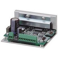
Manufacturer Part Number
BS1D200P10
Description
Stepper Motor Driver
Manufacturer
SANYO DENKI - SANMOTION
Datasheet
1.BS1D200P10.pdf
(64 pages)
Specifications of BS1D200P10
No. Of Phases
Two
Output Voltage Max
40V
Output Current
10mA
Supply Voltage Min
24VDC
Operating Temperature Max
50°C
Length/height, External
29mm
External Width
64mm
Current Limit Max
3A
Supply Voltage Range
24VDC To 36VDC
Rohs Compliant
Yes
Approval Bodies
CE / CUL / EN / TUV / UL
External Depth
56mm
Lead Free Status / RoHS Status
Lead free / RoHS Compliant


・
・
・
・
・
2-phase STEPPING SYSTEMS
■
■
■
■
IC for stepping motor
Item
Source voltage-1
Source voltage-2
Input voltage
Phase current
Operating
temperature on
PCB
Junction
temperature
Conservation
temperature
Pin No.
1.
2.
3.
4.
5.
6.
7.
8.
9.
10.
11.
Terminal name
V
Clock
CW / CCW
Reset
Return
Enable
M
M
Sine wave driven micro-step driver.
The current detection resistor is incorporated.
MOSFET is used for the power driving circuit to reduce heating.
Totally packaged to reduce parts for the peripheral circuit.
Enables selection from the 5 various excitation modes by the external bit signal.
ref
0I
01
、
Characteristics
Maximum Rating
Dimensions
Each Terminal Function
M
02
Terminal name
B
B
P.GND A
P.GND B
A
A
V
V
Mode 1
Mode 2
Mode 3
CC2
ref
Symbol
V
V
V
I
T
T
T
OH MAX.
stg
CC1 MAX.
CC2 MAX.
in MAX.
C MAX.
j MAX.
Specifications
Function
Motor current setting input
Motor driving pulse input
Motor rotation direction setting input
System reset
Forced return to phase origin
Power OFF input
Phase origin monitor output
Monitor output on phase energization status
[
unit: mm
Condition
V
With no signal
Logic input terminal
0.5sec, 1pulse, V
−
−
−
CC2
=
(
0V
Tc=25
(
inch
Pin No.
12.
13.
14.
15.
16.
17.
18.
19.
20.
21.
22.
℃)
) ]
CC1
applied
HIC for the 2-phase stepping motor
PMM2301
Micro Step
Unipolar
Terminal name
V
V
Clock
CW
Reset
Return
Enable
M
M
M
GND
CC2
CC2
Rated value
52
7
7
4
105
150
- 40 to 125
0I
01
02
/
CCW
Unit
V
V
V
A
℃
℃
℃
Functioning condition
−
Mode 3 = H level : Operates at rising edge
Mode 3 = L level : Operates at rising and falling edges
Reset
Forced shift to the origin of the present energization phase with Return = H
Enable
Outputs level signal on the present phase energization status.
Phase
coordinate
M01
M02
H level = CW rotation
L level = CCW rotation
L level output at the phase origin.
=
=
"L"
"L"
■
Item
Source voltage-1
Source voltage-2
Input voltage
Phase current
Clock frequency
Withstand voltage of
phase driver
(2–.14)
2–3.6
Recommended Operating Conditions
A phase
H
L
(.35)
[9]
1
(21
PMM2301
21
x
.08=1.68)
(2.64)
(2.36)
x
2=42
67
60
Symbol
V
V
V
I
Clock
V
B phase
L
H
OH
CC1
CC2
IH
DSS
22
0.5 –
(
.02 –
+0.2
Condition
With signal
With signal
−
Duty 50
−
−
0.05
+.008
.002
)
A phase
L
L
%
(.35)
9
(.11)
Rated value
10 to 45
5.0
0 to V
3
DC to 50
100
(
2.9
.016 –
0.4 –
(
B phase
H
H
Ta=25
±
+0.2
+.008
0.05
CC2
5
.002
%
℃)
)
Unit
V
V
V
A
kHz
V
58
Related parts for BS1D200P10
Image
Part Number
Description
Manufacturer
Datasheet
Request
R

Part Number:
Description:
MINISTEP BIPOLAR CHOPPER DRIVE, 2, 110 TO 230VAC
Manufacturer:
SANYO DENKI - SANMOTION
Datasheet:

Part Number:
Description:
MINISTEP BIPOLAR CHOPPER DRIVE, 2, 25 TO 45VDC
Manufacturer:
SANYO DENKI - SANMOTION
Datasheet:
Part Number:
Description:
MINISTEP BIPOLAR CHOPPER DRIVE, 2, 25 TO 45VDC
Manufacturer:
SANYO DENKI - SANMOTION
Datasheet:
Part Number:
Description:
MINISTEP BIPOLAR CHOPPER DRIVE, 2, 100 TO 120VAC
Manufacturer:
SANYO DENKI - SANMOTION
Datasheet:

Part Number:
Description:
CONTROLLER, STEPPER, 4 OPTIONAL
Manufacturer:
SANYO DENKI - SANMOTION
Datasheet: