BS1D200P10 SANYO DENKI - SANMOTION, BS1D200P10 Datasheet - Page 58
BS1D200P10
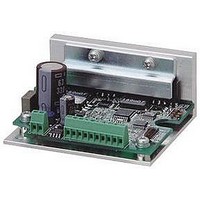
Manufacturer Part Number
BS1D200P10
Description
Stepper Motor Driver
Manufacturer
SANYO DENKI - SANMOTION
Datasheet
1.BS1D200P10.pdf
(64 pages)
Specifications of BS1D200P10
No. Of Phases
Two
Output Voltage Max
40V
Output Current
10mA
Supply Voltage Min
24VDC
Operating Temperature Max
50°C
Length/height, External
29mm
External Width
64mm
Current Limit Max
3A
Supply Voltage Range
24VDC To 36VDC
Rohs Compliant
Yes
Approval Bodies
CE / CUL / EN / TUV / UL
External Depth
56mm
Lead Free Status / RoHS Status
Lead free / RoHS Compliant


57
2-phase STEPPING SYSTEMS
HIC for the 2-phase stepping motor
PMM2101
■
■
The overheat protection circuit outputs an alarm signal at +125
at +150
■
●
●
●
●
Peak reverse voltage
IC for stepping motor
Item
"H"level input voltage
"L"level input voltage
"H"level input current
"L"level input current
Reference voltage (V
Current detection (V
Forward direction voltage of FET diod
High output saturating voltage
Low output saturating voltage
Low output saturating voltage
Power current to controller section
Alarm terminal current
Overheat alarm operating temperature
Overheat protection stop temperature
Applicable
R1,R2
R3,R4
R7,R8
Output current
Reverse recovery time
Refer to page 53 for the PMM8713PT specifications.
Recommended circuit constants for PMM2101
Determine on the R5 and R6 constants referring to the Vref-
output current characteristics.
Determine on D1 to D4.
Electrical Characteristics
Overheat Alarm Output
Example of Application Circuit
Energization
℃
.
Driving input
mode setting
Reset input
27-pin
s
5V
≧
ref
) input current
) input current
1A
5V
Specifications
Constant
5W
1
1
≧
/
/
100V
GND
External pull-up resistor
4W
4W
≦
(approximate 10kW)
0.68
+
100ns
3.9k
15k
1
2
3
4
5
6
7
9
Ω
PMM8713PT
Full Step / Half Step
16
Open collector output
Ω
Ω
V
CC2
GND
8
(+5V)
PMM2101
14
15
13
12
11
10
Applicable
C1, C2
C3, C4
C5
Symbol
V
V
I
I
I
I
V
V
V
I
I
I
−
−
IH
IL
ref
S
R
CC2
alm
IH
IL
F
ce (sat)H
ce (sat)L
(
P.GND
Ta=25
24V
R5
R6
GND
External output
5V
)
Condition
V
V
V
V
V
V
I
I
I
V
V
V
V
−
−
F
C
C
CC2
CC2
CC2
CC2
CC2
CC2
CC1
OUT
CC2
CC2
=
=
=
Constant
1000pF
3300pF
330
=
=
=
=
=
=
1A
1A
1A
=
=
=
=
13
C1
+
μ
5V
5V
5V
5V
5V
5V
60V
= 5V
5V
60V
C5
25
24
22
4
3
6
9
PMM2101
F
、
、
、
、
、
2
R1
R3
、
、
(
V
V
V
V
V
V
I
I
ref
S
V
during circuit operation
alm
26
11 15
=
=
=
OUT
℃
RS
=
=
5V
0V
0V
=
=
21
0V
at the internal junction in the IC, and activates
0.5V
0V
R2
R4
0V
GND
7
19 8
●
●
1.2
1.0
0.8
0.6
0.4
0.2
0.0
C2
0.1 0.2 0.3 0.4 0.5 0.6 0.7 0.8 0.9
Transistor ON during alarming
The alarming signal output and overheat protection circuit
recover automatically when the temperature lowers.
23
Vce
lalm : 2mA MAX.
5V
10
12
14
18
5
V
1
ref
20
–Output current characteristics
(
ON
V
ref
)
)
C3
R8
C4
R7
Voltage (V)
: 0.5V MAX.
GND
Rating
MIN.
2.7
0
−
−
−
−
−
−
−
−
−
−
−
−
−
Orange
D1~D4
Yellow
Blue
Red
Stepping motor
Standard
−
−
−
−
−
−
1.3
1.0
1.0
−
−
−
−
125
150
(
MAX.
V
1.0
10
-50
-10
-10
1.5
1.4
1.3
10
10
75
2
−
−
motor excitation OFF
CC2
Unit
V
V
μ
μ
μ
μ
V
V
V
μ
μ
mA
mA
℃
℃
A
A
A
A
A
A
)
Related parts for BS1D200P10
Image
Part Number
Description
Manufacturer
Datasheet
Request
R

Part Number:
Description:
MINISTEP BIPOLAR CHOPPER DRIVE, 2, 110 TO 230VAC
Manufacturer:
SANYO DENKI - SANMOTION
Datasheet:

Part Number:
Description:
MINISTEP BIPOLAR CHOPPER DRIVE, 2, 25 TO 45VDC
Manufacturer:
SANYO DENKI - SANMOTION
Datasheet:
Part Number:
Description:
MINISTEP BIPOLAR CHOPPER DRIVE, 2, 25 TO 45VDC
Manufacturer:
SANYO DENKI - SANMOTION
Datasheet:
Part Number:
Description:
MINISTEP BIPOLAR CHOPPER DRIVE, 2, 100 TO 120VAC
Manufacturer:
SANYO DENKI - SANMOTION
Datasheet:

Part Number:
Description:
CONTROLLER, STEPPER, 4 OPTIONAL
Manufacturer:
SANYO DENKI - SANMOTION
Datasheet: