BS1D200P10 SANYO DENKI - SANMOTION, BS1D200P10 Datasheet - Page 7
BS1D200P10
Manufacturer Part Number
BS1D200P10
Description
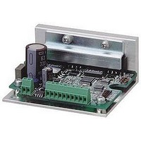
Stepper Motor Driver
Manufacturer
SANYO DENKI - SANMOTION
Datasheet
1.BS1D200P10.pdf
(64 pages)
Specifications of BS1D200P10
No. Of Phases
Two
Output Voltage Max
40V
Output Current
10mA
Supply Voltage Min
24VDC
Operating Temperature Max
50°C
Length/height, External
29mm
External Width
64mm
Current Limit Max
3A
Supply Voltage Range
24VDC To 36VDC
Rohs Compliant
Yes
Approval Bodies
CE / CUL / EN / TUV / UL
External Depth
56mm
Lead Free Status / RoHS Status
Lead free / RoHS Compliant


Specifications
※
※
※
Basic
specifications
Function
I/O signals
1
□
2
3
Note that the power voltage must not exceed 24VDC + 10% (26.4VDC).
If the driver is placed in a box, the temperature inside the box must not exceed this specified range.
The maximum input frequency is 250k pulse/s.
60mm
PS
1・・・・19
2・・・・20
2
(
RSW
C
4
1
Part number
Input source
Getaway torque
Environment
Mass
Protection function
LED indicator
Command pulse input signal
Power down input signal
Step angle setting selection input
FULL/HALF setting selection input
EMG input signal
BUSY output signal
Phase origin monitor output signal
Alarm output signal
□
DS
1.65inch
CN1:POWER
Manufacturer:JST
CONNECTOR:S02B-PASK-2
(
Weight
CN2:I/O
Manufacturer:JST
CONNECTOR:SM20B-SHLDS-GW-TF
(
(
Flange size
Note1
)
(
Protection class
Operation environment
Applied standards
Operating ambient temperature
(
Conservation temperature
Operating ambient humidity
Conservation humidity
Operation altitude
Vibration resistance
Impact resistance
Withstand voltage
Insulation resistance
A
Note2
(
)
)
)
AL
)
(
)
)
PD
(
)
Note3
(
(
(
EXT
MON
)
F/H
)
)
)
88
+2
(
0
3.46
DB21M142S-01
DC24 V
2 MAX.
Class I
Installation category
EN61010-1
0 to + 40
- 20 to + 60
35 to 85%RH
10 to 90%RH
1000 m
Tested under the following conditions ; 4.9m/s2, frequency range 10 to 55Hz, direction along X, Y
and Z axes, for 2 hours each
Not influenced at NDS-C-0110 standard section 3.2.2 division C .
Not influenced when 1500V AC is applied between power input terminal and cabinet for one
minute.
10M ohm MIN. when measured with 500V DC megohmmeter between input terminal and cabinet.
0.5kg
Against driver overheat
Alarm monitor
Photo coupler input method, input resistance 220
Input signal voltage : H = 4.0 to 5.5V, L = 0 to 0.5V
Photo coupler input method, input resistance 470
Input signal voltage : H = 4.0 to 5.5V, L = 0 to 0.5V
Photo coupler input method, input resistance 470
Input signal voltage : H = 4.0 to 5.5V, L = 0 to 0.5V
Photo coupler input method, input resistance 470
Input signal voltage : H = 4.0 to 5.5V, L = 0 to 0.5V
Photo coupler input method, input resistance 470
Input signal voltage : H = 4.0 to 5.5V, L = 0 to 0.5V
Photo coupler input method, input resistance 220
Input signal voltage : H = 4.0 to 5.5V, L = 0 to 0.5V
Open collector output by photo coupler
Output signal standard : Vceo = 30V MAX., Ic = 20mA MAX.
Open collector output by photo coupler
Output signal standard : Vceo = 30V MAX., Ic = 20mA MAX.
EARTH TERMINAL
M2.5X0.45X4L
アース線を接続せよ
+.08
.
r
s
.00
e
e
g
p
u
n
o
q
i
r
(
i
d
p
1.5±0.25 (.06±.01)
n
n
)
h
u
c
o
e
7±0.25 (.27±.01)
必ず
e
r
s
(
1.10lbs
t
g
U
℃
±
3280 feet
10
℃
(
(
%
)
no condensation
no condensation
)
(
MAX. above sea level
(
□
42
20.6±0.5 (.81±.02)
over-voltage category
(EFFECTIVE
15
LENGTH)
)
+1
(
R4MIN.
0
.59
+.04
.00
)
)
)
0.1
A
A
)
: II, pollution degree : 2
0.025
0.075
DB22M162S-01
3 MAX.
0.87kg
Ω
Ω
Ω
Ω
Ω
Ω
A
(
1.92lbs
)
47.1±0.13 (1.85±.01)
60±0.5 (2.36±.02)
(
□
60
5.8±0.15(.23±.01)
)
4−φ4.5 0
+0.5
(
4−φ.18 .00
+.02
)
6
Related parts for BS1D200P10
Image
Part Number
Description
Manufacturer
Datasheet
Request
R

Part Number:
Description:
MINISTEP BIPOLAR CHOPPER DRIVE, 2, 110 TO 230VAC
Manufacturer:
SANYO DENKI - SANMOTION
Datasheet:

Part Number:
Description:
MINISTEP BIPOLAR CHOPPER DRIVE, 2, 25 TO 45VDC
Manufacturer:
SANYO DENKI - SANMOTION
Datasheet:
Part Number:
Description:
MINISTEP BIPOLAR CHOPPER DRIVE, 2, 25 TO 45VDC
Manufacturer:
SANYO DENKI - SANMOTION
Datasheet:
Part Number:
Description:
MINISTEP BIPOLAR CHOPPER DRIVE, 2, 100 TO 120VAC
Manufacturer:
SANYO DENKI - SANMOTION
Datasheet:

Part Number:
Description:
CONTROLLER, STEPPER, 4 OPTIONAL
Manufacturer:
SANYO DENKI - SANMOTION
Datasheet: