BS1D200P10 SANYO DENKI - SANMOTION, BS1D200P10 Datasheet - Page 12
BS1D200P10
Manufacturer Part Number
BS1D200P10
Description
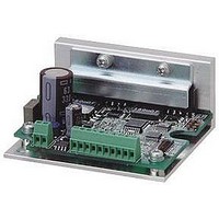
Stepper Motor Driver
Manufacturer
SANYO DENKI - SANMOTION
Datasheet
1.BS1D200P10.pdf
(64 pages)
Specifications of BS1D200P10
No. Of Phases
Two
Output Voltage Max
40V
Output Current
10mA
Supply Voltage Min
24VDC
Operating Temperature Max
50°C
Length/height, External
29mm
External Width
64mm
Current Limit Max
3A
Supply Voltage Range
24VDC To 36VDC
Rohs Compliant
Yes
Approval Bodies
CE / CUL / EN / TUV / UL
External Depth
56mm
Lead Free Status / RoHS Status
Lead free / RoHS Compliant


11
(
2-phase STEPPING SYSTEMS
SET UP
■
The functions according to the specification can be selected with this Dip switch.
Confirm the ex-factory setting as follows.
Input pulse mode selection
This switch setting is only effective in pulse stream I/F
mode.
Low vibration and smooth operation is enabled even by the rough
resolution setting
This switch setting is only effective in pulse stream I/F mode.
For parallel I/F mode and serial I/F mode, this is usually a low
vibration operation.
※
Select the Motor winding current value when inputting the power down
signal.This switch setting is only effective in pulse stream I/F mode.
※
※
The operation mode is selected.
※
◎
1
2
3
4
5
F / R
ON
OFF
e.g. 1 division, 2 division
LV
ON
OFF
PD
ON
OFF
I.SEL
OFF
ON
driving pulse will be carried out inside the Driver. Therefore, the Motor
movement delays for the time of 3.2ms pulse per input pulse. Note that
depending upon the combined Motor, load,driving profile and etc, it may
take a while until the shaft is adjusted when the Motor stops.
I/F mode and serial I/F mode there is no delay
PD function
is enabled by PD input signal ON
Output signal connector
the other current settings except for alarms. The operational status may
not be maintained such as power swing due to output torque drop or
lower operation due to Motor current OFF
attention to the input timing of the power down signal in addition that
the security device should be installed to the machine.
By turning on the EORG, excitation phase when power OFF is saved.
Change the operation mode selection switch after cutting off the driver
s power supply.
When LV select is ON
Input mode select
Low vibration mode select
Power down select
Excitation select
,
Specification
For pulse stream I/F mode
Function Select Dip Switch
6
Operation mode selection
Input pulse mode
1 input mode
2 input mode
Operation
Low vibration operation
Micro step operation
Motor winding current
Current value by rotary switch STP
0A
S.SEL
OFF
ON
(
(
the setting selected by PD of the function select dip switch
−
Power OFF
(
Operation mode
Pulse stream I/F mode
Parallel I/F mode
Serial I/F mode
low vibration mode
(
(
(
(
(
CK,U/D
CW,CCW
CN2
)
)
EORG
(
F/R
.
PD
)
. Power down signal input is prior to all
(
)
)
)
built-in photo coupler ON
)
)
(
LV
(
(
)
unexcited Motor
)
, operational process of
I.SEL, S.SEL
)
(
Power Low
1
2
3
4
5
6
F/R
LV
PD
EORG
I. SEL
S. SEL
)
)
)
OFF
(
of Input/
)
. Pay extra
In parallel
ON
)
OFF
OFF
OFF
OFF
OFF
OFF
2 input mode (CW/CCW pulse)
Micro step operation
Power OFF
Phase origin excitation
Pulse stream I/F mode
The communication speed of serial communication is
set.
※
※
◎
Switch
F/R
LV
PD
The setting change after the power supply is turned on is invalid.
It does not function as a F/R, LV, and PD.
The communication speed of pulse stream I/F mode is fixed at 9600bps.
For parallel I/F mode or serial I/F mode
Set value
OFF
ON
OFF
ON
OFF
ON
9,600
○
○
○
Communication speed(bps)
19,200
○
○
○
38,400
○
○
○
115,200
○
○
○
Related parts for BS1D200P10
Image
Part Number
Description
Manufacturer
Datasheet
Request
R

Part Number:
Description:
MINISTEP BIPOLAR CHOPPER DRIVE, 2, 110 TO 230VAC
Manufacturer:
SANYO DENKI - SANMOTION
Datasheet:

Part Number:
Description:
MINISTEP BIPOLAR CHOPPER DRIVE, 2, 25 TO 45VDC
Manufacturer:
SANYO DENKI - SANMOTION
Datasheet:
Part Number:
Description:
MINISTEP BIPOLAR CHOPPER DRIVE, 2, 25 TO 45VDC
Manufacturer:
SANYO DENKI - SANMOTION
Datasheet:
Part Number:
Description:
MINISTEP BIPOLAR CHOPPER DRIVE, 2, 100 TO 120VAC
Manufacturer:
SANYO DENKI - SANMOTION
Datasheet:

Part Number:
Description:
CONTROLLER, STEPPER, 4 OPTIONAL
Manufacturer:
SANYO DENKI - SANMOTION
Datasheet: